


Technical Daring

As watershape designs become increasingly creative and complex, the demand for more precise methods of engineering their structures has grown as well. To meet that need, observe Ron Lacher and Aaron Cowen of Pool Engineering, experts like them are turning to advanced three-dimensional modeling technology – systems so sophisticated that they make it possible to develop plans for daring projects such as they one they describe here.
It’s easily the most sophisticated watershape structure we’ve ever engineered.
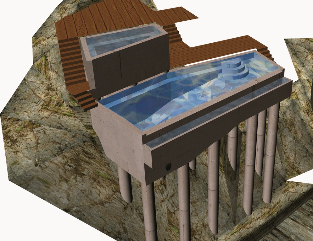
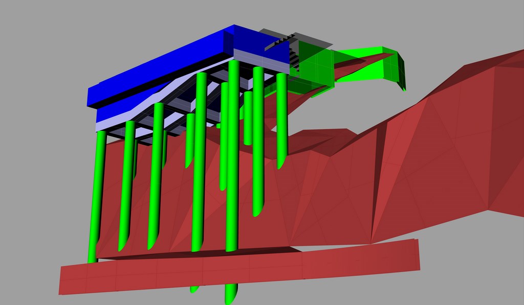
The pool/spa combination, not yet built, will rise some 50 feet above grade on a cliff behind a home in the densely populated Hollywood Hills near downtown Los Angeles. As conceived, the vanishing-edge pool will sit a full ten feet below the spa in a complex monolithic structure. Supporting the entire affair will be 18 exposed concrete columns on a friction-pile-and-grade-beam foundation that, from below, will look a lot more like a freeway overpass than a watershape.
The project is so tricky and the access so difficult that, in fact, we’re uncertain it will ever be built. From our perspective as engineers, however, it’s important to note that, even a few years ago, there was no method familiar to the pool and spa industry that would have allowed us even to dream about such a structure with much confidence.
For the past three years, however, our work at Pool Engineering of Anaheim, Calif., on behalf of designers and builders has been enhanced by advanced computer modeling technology. In the case of this project, we were forced to stretch our own technical capacity with this technology to all-new levels to design a structure that would not only bear up under its own weight, but also withstand the near certainty of a large earthquake.
In a project such as this, there is simply no room for error.
HIGH STAKES
One key feature of this modeling technology is the fact that it lets us visualize entire structures in three dimensions. That’s great, but the real value comes in the fact we’re also able to run modeling programs that test a proposed structure against a range of structural stresses and forces that will influence its performance under a variety of conditions.
The programs we use perform literally millions of calculations that examine extremely small segments of a structure in exhausting detail. This enables us to see, in three dimensions, exactly where a structure will have the greatest chance of failure – thus allowing us to adjust the design to correct deficiencies in those areas.
With a project of this complexity and apparent risk, this process is the only way we can determine where we stand and remove any guesswork that might have characterized the process had it been tackled with more conventional techniques.
The traditional design approach might simply have been to overbuild the entire structure and go way beyond what the building codes require. The problem with that approach is that, as you add weight to a suspended structure to overbuild it, you also increase demands on the foundation system required for its support. Things get even more complicated with a structure that’s suspended high in the air and holds water.
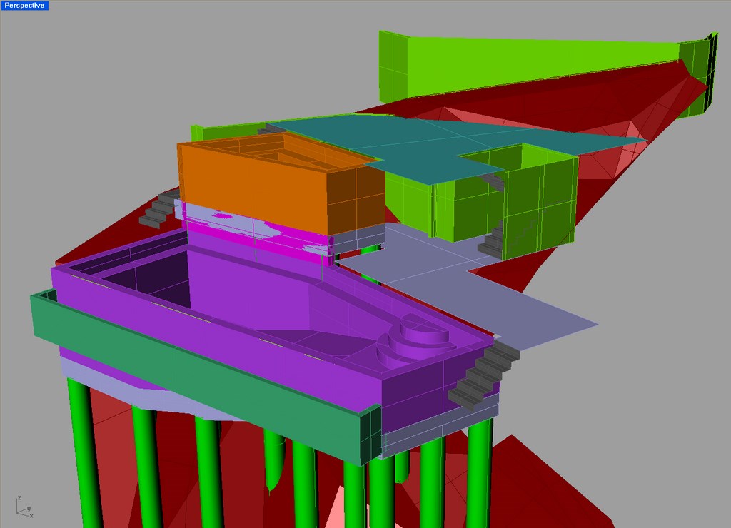
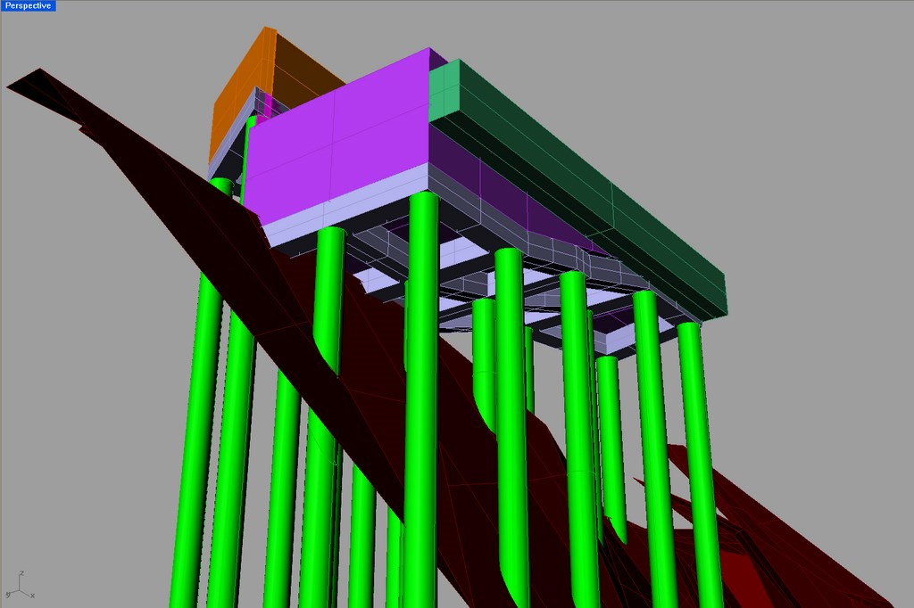
| The first phase of the modeling process involves generation of a set of ‘solid’ structures in three dimensions, as extrapolated from drawings generated by the architects and contractors. The colors highlight different ‘layers’ of the composition and enable us to see things very clearly, even at this early stage. |
As we’ve learned through our modeling analyses, certain areas in a structure – and it’s often hard to anticipate exactly which areas – will experience the highest stress. Adding mass to a reinforced concrete structure in the process of exceeding code requirements will increase the stress on those areas and might actually increase chances of catastrophic failure rather than reduce them.
We don’t believe in that sort of compensatory overkill. Experience shows that a properly, precisely designed structure will be the most reliable (and cost-effective) to build – and that’s what we set out to deliver in approaching this project. For starters, we were required by building codes to calculate “hydrodynamic forces” – basically the forces exerted on the structure by the motion of water moving within it during an earthquake.
In this case, we ended up running 29 different loading combinations, each requiring a completely different set of calculations, to cover seismic events moving in a variety of directions as well as the impulsive and convective hydrodynamic forces. (The impulsive force refers to the effect of the water’s mass being pushed; the convective force accounts for the sloshing of the water back and forth and how water rising on one side and lowering on the other will influence the structure.)
In addition, we also had to calculate basic dead and hydrostatic loads; bending, axial and shear loads; soil-creep loads on the pilings; and a variety of combined scenarios – the full list of load analyses. If performed using traditional methods, making these calculations would have involved making lots of assumptions; that was not the case using finite element analysis technology.
BIT BY BIT
Before running these calculations, however, we had to do quite a bit of research. We obtained documents from the Nuclear Regulatory Commission, for example, taking advantage of its extensive studies of concrete structures that contain the water for nuclear reactors. We also relied heavily on a publication from the Portland Cement Association, Design of Liquid-Containing Concrete Structures for Earthquakes Forces, which provides mathematical formulas that define input loadings for seismic stresses.
We also worked extensively with our software providers to establish protocols for calculations that would meet basic codes, and we modified major portions of the software to work with swimming pool structures, which are unique in a great many ways with respect to the challenge of structural engineering. In all, we amassed 80 pages of standard calculations in reference to specific codes.
Although most people (and even most watershapers) don’t generally think of swimming pools as high-tech structures as compared to, say, nuclear reactors, in some respects our pools, spas and fountains can be more technically challenging.
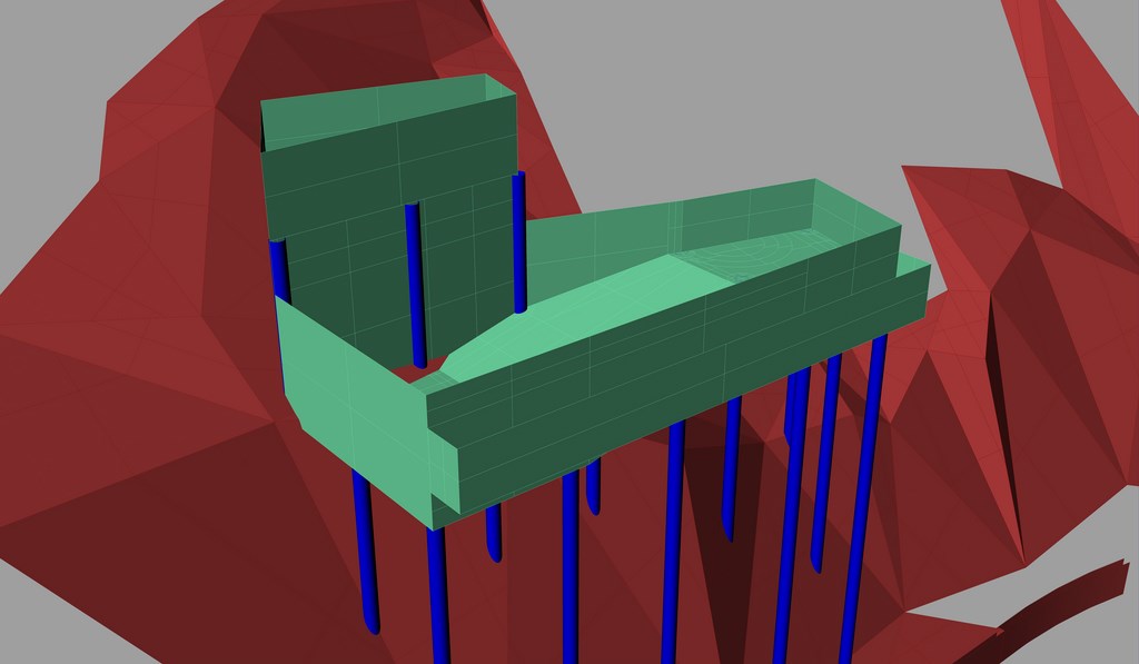
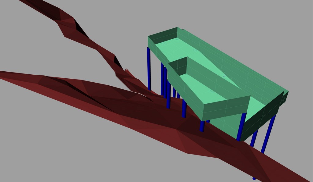
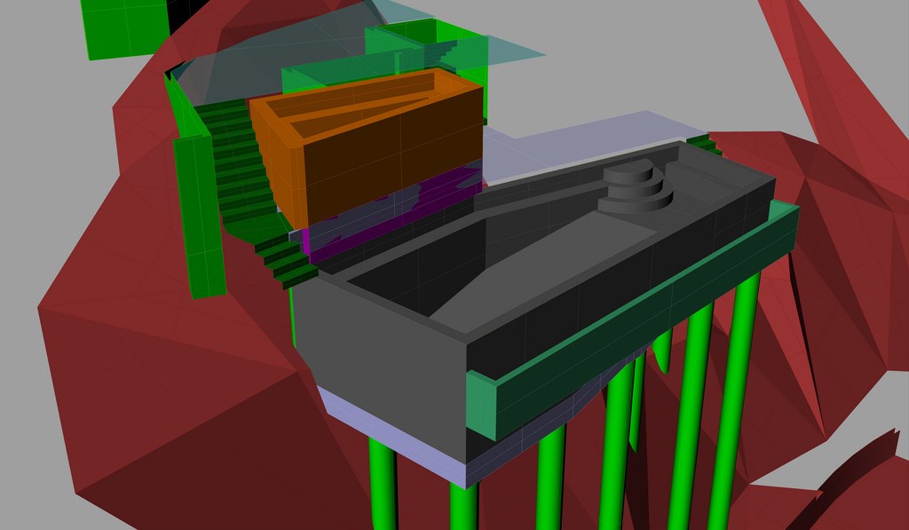
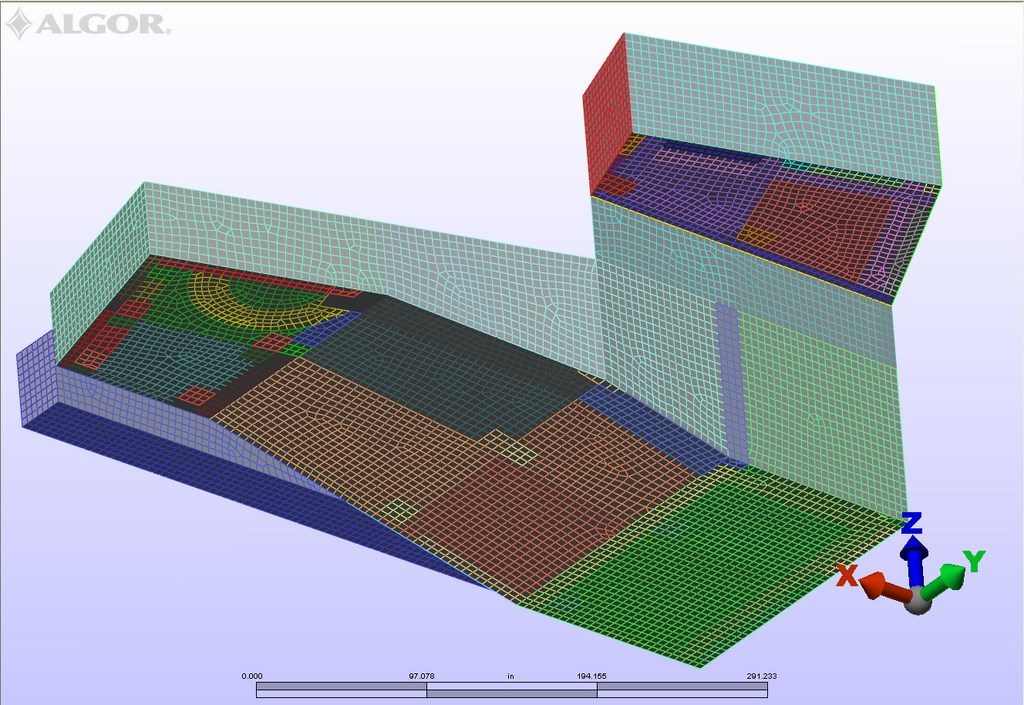
| In the second step of the modeling process, we produce a mid-line mesh based on the centerlines of walls and floors. This intermediate stage is critical: It gives us information on basic structures – and on dimensional planes that we feed into the next stage of the analysis. |
In most industrial, military or commercial applications, large concrete structures are typically either rectilinear or round with flat bottoms and sides. By contrast, most swimming pools are composite shapes with varying depths and a variety of internal and external contours. For this project, we’ve had to examine all of the various dynamic forces section by section, which greatly complicated the entire design process.
We began our computer studies with a program called Rhinoceros 3D, to which we input basic design features as provided by the architects and contractors. This enabled us to generate a solid, three-dimensional model and let us “see” the structure from a variety of perspectives, estimate its basic mass properties and provide the basis for subsequent modeling iterations.
From there, we converted results to a mid-plane mesh, which is basically a model that’s based on all the centerlines of walls and floors. That model was then transferred into a second modeling program, this one called Algor, which broke the design down into plates (or finite elements).
The majority of the structural modeling and engineering calculations were carried out in a third program known as RISA 3D. This program provides more control over loading combinations and also performs specific reinforced-concrete design calculations for the beams and columns. The transfer of data between all three programs was performed with a special proprietary translating program designed by our in-house computer-programming staff.
REINFORCING LOGIC
Collectively, this stage is where the bulk of the calculating took place.
In this case, we generated tens of thousands of plates, each one roughly four inches by four inches and each one of which was run through thousands of specific calculations. (That size can be adjusted, but the smaller the elements, the vaster the number of calculations required generating the model. In our case, we actually pushed the processing capacity of the software and our computers. Had we used a finer mesh of plates, the demand for computing capacity would’ve gone way beyond what the software and our systems could have handled.)
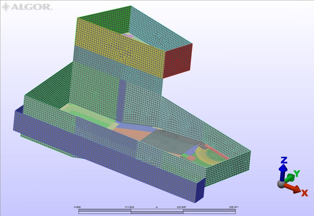
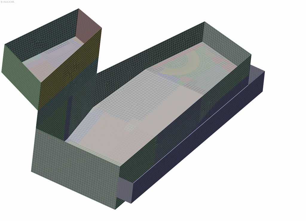
| The information available once the second step is complete is then transferred to the Algor program, which takes the midline information and generates information on individual ‘plates’ that are part of the structure, allowing each of these small units to be analyzed individually. The mesh is later transferred to the RISA program for the actual analysis. |
There are so many variables in the modeling process that we habitually double- and triple-check the process by running various calculations using standard methods: In other words, we want to make certain that the loads we’re seeing in the models match the outputs derived from basic formulas, because mistakes at one stage of the process will be exacerbated in subsequent stages.
Moreover, we were translating data between three programs that work in different units of measurement, so it was critical to be certain all of the mathematic translations were correct. Just consider the consequences of translating something from inches to feet or inches to millimeters through a simple error: The cascade of errors that would flow from such a miscue could result in a design based on entirely erroneous data – not something to be desired.
The formulas and calculations are so complex and numerous, it would take literally hundreds of pages to describe even a portion of them. Indeed, with this project and all of its structural complexities, we’ve pushed the limits of our ability to use and master this technology.
Interestingly, the process has also reinforced in mathematical terms a range of theoretical assumptions engineers are taught in the classroom. In analyzing the loads on the caissons, for example, the system demonstrates that the greatest lateral stresses are placed on the shortest pilings near grade – in this case the columns right below the wall separating the pool from the spa.
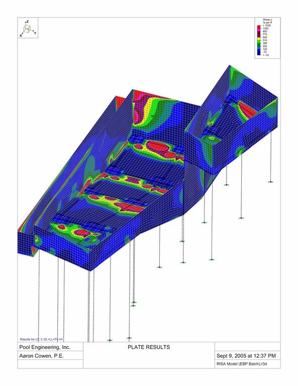
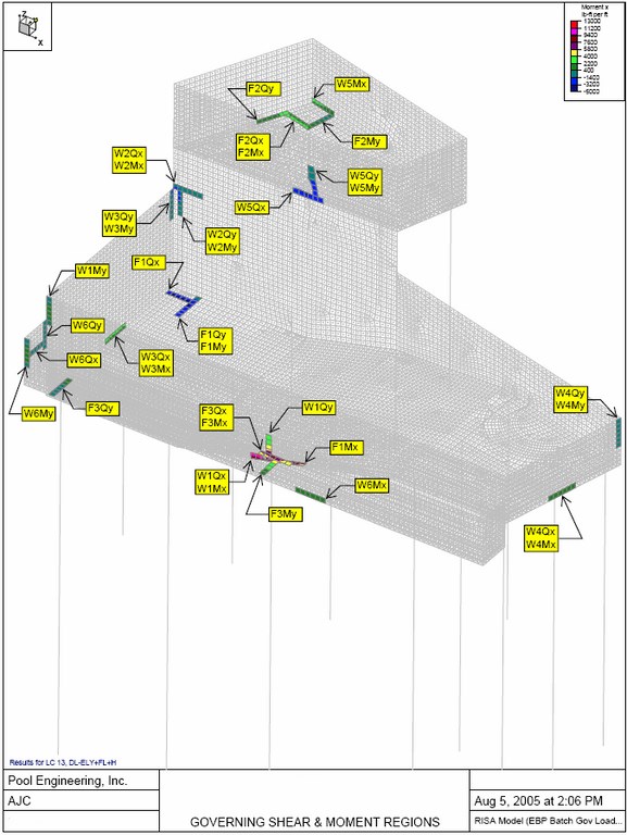
| When the RISA program completes its analytical calculations, we gain access to stress contour maps such as these in which colors are used to indicate structural stresses induced by a range of different seismic scenarios. |
Most people would assume that the longest columns, some reaching 50 feet above grade, would experience the greatest stresses because they have the greatest spans. In fact, the opposite is true: Because shorter columns are less flexible than longer ones, they absorb far more of the shear force.
In this case, the modeling showed us stresses on the shortest columns that were several factors greater than those affecting the long ones. Thus, what was once something we understood only on a conceptual or theoretical basis has now been proved to us mathematically.
The process also can demonstrate where basic assumptions are wrong. In my earliest thinking about the caisson structure, for example, I thought that 24-inch diameters would be the solution. Once we got into the numerical analysis, however, we saw that 30-inch columns would be required due to the very high seismic loading from the mass of the water.
HURDLES TO COME
Because the engineering plan is based on rectilinear geometry with planes intersecting corners, we also were able to recognize that most of the spots experiencing the greatest stress are located at corners where loads are transferred across perpendicular intersections. In other projects that have more rounded or free-form shapes, we would see an entirely different profile of major stress points.
The significance of all this is that we can use the system’s identification of points of high stress to design structural details that can accommodate those stresses. We’ll use requirements for those critical areas as the basis for the steel and concrete structures we specify for the rest of the vessel.
This has practical implications as well: It makes sense to maintain relative uniformity in the steel schedules to reduce chances of confusing installers on site. After all, this sort of project is complicated and challenging enough all on its own.
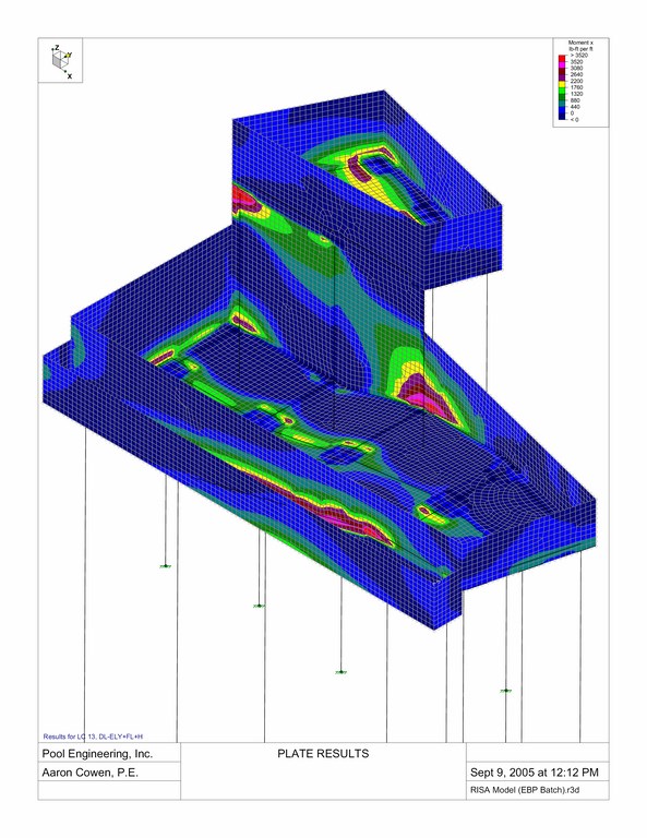
| Our modeling is completed by using the RISA program to generate very specific information we can use to get a handle on loading combinations for the overall structure and to generate specific information about the reinforced-concrete structures of the beams and columns. |
To be sure, this project is unique in its structural requirements. Simple designs don’t need this sort of attention, nor would they come close to justifying an investment in this level of analysis. In this case, the project gave us an opportunity to explore the uses of this technology in a real-world situation – and we welcomed that opportunity.
We’re confident that when this project breaks ground and the support structure and vessels rise above the hillside, the contractor will be working with reliable plans that, if executed as specified, will result in a structurally sound installation.
Naturally, on-site supervision is crucial to ensure that the plans are actually executed to the necessary level of detail. We know that when the work begins, we’ll stop by and visit the site repeatedly to observe how the design is playing out in the field with respect to installation.
That’s an entirely separate story from what’s happened so far in the precise realm of plate analysis. This site offers incredible challenges with respect to access, and it’s immeasurably difficult to work on such steep grades. At this point, construction may require the steel structures for the pilings to be fabricated off site and flown in by helicopter – and that’s just the beginning of the practical hurdles that would confront any contractor charged with bringing this plan to fruition.
Even if the challenges prove too great and the watershape is never built, the background process of designing the structure has proved invaluable to our firm. We’ve learned so much about both computer technology and our own assumptions about structural engineering calculations and design, and we know this knowledge base will transfer over to other projects.
From our perspective, however, our firmest conviction is that what we’ve seen on this project is a glimpse into the future of watershape design.
Ron Lacher is president of Pool Engineering Inc., in Anaheim, Calif. A licensed civil engineer, he spent the first ten years of his career managing large-scale construction projects for a variety of governmental agencies before becoming a pool builder in Southern California. In 1992, Lacher founded Pool Engineering, which specializes in developing structural and engineering plans. Since then, the firm has provided structural documents and details for thousands of residential and commercial swimming pools. He regularly serves as a field expert for California’s Contractor State License Board, insurance companies, homeowners and pool-construction companies. Aaron Cowen is a senior civil engineer for Pool Engineering in Anaheim, Calif., a position he’s held since 1998. He holds a B.S. degree in civil engineering from California State University, Long Beach (1991) and a master’s degree in structural engineering and design practice from the University of California (2004). He has served as design leader for numerous projects, including many that have featured cantilevered concrete decks, thin-wall concrete shells and swimming pool structures that called for drilled piers, grade beams and structural floors. Before taking his current position, Cowen served as an assistant civil engineer for the City of Santa Ana, Calif., where he designed and drafted sewage and water-distribution systems.