


A Pump Primer

Whether you build fountains, streams or Olympic-size swimming pools, you need to install a pump of some kind to make these watershapes work. As fundamental and essential as pumps really are, however, it’s amazing to think how casual many of us in the trade are when it comes to knowing about how they work and how their performance characteristics differ.
We’ve all heard and used terms like “energy efficient,” “high head” and “self-priming,” but for the most part, the real meanings of those words get lost in the competitive marketing blizzard that surrounds these products. Without a clear understanding of how pumps are designed and how they do their job, these distinctions are no more than words on a label – and that’s not the way it should be.
As watershapes become ever more complex and hydraulically challenging, cutting through the hype to find out what truly makes pumps work becomes even more important: No matter how beautiful a design may be, without a properly selected and installed pump working at the heart of the system, the best work will fall short in performance and ultimately in customer satisfaction.
In the following, I’ll define pump technology in a way that sheds light on the important differences in basic pump design and function – and how you can use the choices available to you to the greatest possible advantage and effect.
DEFINING TYPES
Let’s begin this exploration of pump technology by crossing some technical terrain and reviewing a bit of physics.
In engineering terms, a pump is a mechanical device used to move liquid and raise that liquid’s pressure. To achieve this, the pump must accomplish a series of basic energy transformations.
In the first, the input energy to the pump’s driver is converted to motor-shaft output in the form of horsepower or torque. (In most cases, the driver is powered by electricity, but pump drivers can be powered by air, steam, hydraulic fluid or diesel-engine oil). This shaft in turn rotates an impeller, a component that is quite familiar to most anyone who’s ever worked on a pump.
The second energy transformation takes place in the pump, where the rotating impeller causes the liquid to pick up speed as it passes through. This increase in water velocity raises the kinetic energy of the liquid.
Next, as the liquid exits the impeller into a casing known as the volute, a diffusion process takes place. In other words, as the impeller rotates, the outlet tip of the impeller discharges water into the pump housing where the flow area increases. This diffusion or expansion of the flow area causes the water’s velocity to decrease, thus converting some of the kinetic energy into pressure energy. (Despite the decreased water velocity, it’s important to note that the water’s velocity is still higher now than when it first entered the pump.) This is what results in the pump’s flow and head (or pressure) characteristics.
That all sounds simple and familiar enough to anyone who has spent time with watershapes, but to understand the implications of these energy transformations fully, we need to back up a step and look at the basic ways that pumps are categorized and what those classifications really mean.
The Hydraulic Institute, which acts as the pump industry’s trade association, classifies pumps in two ways, as dynamic pumps and positive-displacement pumps. Dynamic pumps continuously add energy to the liquid; positive-displacement pumps periodically add energy to the liquid by the use of direct force.
In the swimming pool industry and the watershaping trades, we use dynamic pumps – in other words, our pumps work continuously once the system is turned on. For the most part, our dynamic pumps are of the centrifugal type, which work by means of kinetic energy. By contrast, you might be familiar with positive-displacement pumps of the reciprocating-piston type, as in some chemical feeders. Here, the force is projected directly on the liquid as the piston moves back and forth, thus raising the liquid’s pressure.
CENTRIFUGAL FORCES
By far, watershapers are most familiar with dynamic pumps of the centrifugal type. These are in fact the mainstays of the watershaping industry.
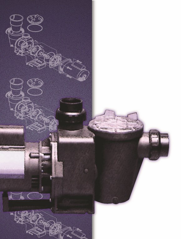
In simple terms, a centrifugal pump consists of the aforementioned impeller, which is attached to a rotating motor shaft, along with the housing or casing that surrounds it. Water is forced upstream into the pump’s inlet (or suction) side by atmospheric pressure or upstream pressure.
|
Level Variations Setting pumps in situations where the vessels they supply and draw from are on different levels can be difficult. For this, you need a good understanding of total static head and how it relates to your system. When a pump is above its supply source, it has a suction lift assigned to it. If the pump is below its supply source, it has suction head. If it is pushing water uphill to a delivery vessel, it has a static discharge head assigned to it. Total static head is measured from the surface of the supply vessel to the surface of the delivery vessel regardless of the pump’s location.
Figure A shows a system in which the pump is pulling water from a supply vessel below and is pushing it to a delivery vessel above. In this situation, the plumbing should include a check valve in front of the pump to enable it to maintain its prime. If the pump is below both the supply side and the delivery side, as shown in Figure B, it has flooded suction and will not have a problem with priming. You should, however, install ball valves on both the suction and return plumbing in order to isolate the pump for servicing. Moreover, if you position equipment below the water’s level, you must be sure the pump can handle the weight of the water! — S.G. |


As the impeller rotates, the liquid flows through the impeller’s vanes, which generally curve backward in the direction of the rotation. This creates a low-pressure area or void at the impeller’s eye (or inlet). The higher pressure forces water into the void of low pressure and causes the pump to prime.
As the liquid exits the outlet tip of the impeller, it is at its highest velocity. At this point, it enters the pump’s volute, where the aforementioned expansion of the water’s flow area occurs.
Some of the kinetic energy created by the increase in water velocity as it travels through the impeller is transformed into potential energy, causing the pressure energy to increase. Simultaneously, as the water leaves the impeller and travels around the volute, the inner pressure increases. This increased pressure produces an upsurge in what is known as the radial force at the periphery of the impeller.
In layman’s terms, this inner pressure is projected across the surface area of the impeller. The total of these radial forces is what engineers use to calculate the maximum net radial force that the motor shaft and bearings will sustain. Having the radial loads running at a minimum will cause the pump to operate at what is known as its best efficiency point (BEP).
Pumps that are forced to work beyond their BEPs are said have excessive radial bearing loads. Symptoms of this include premature seal failure, bearing failure and shaft deflection. By contrast, pumps operating right at their BEPs are said to deliver optimum flow and pressure while the motor is running at its proper amperage.
PRESSURE AGAINST FLOW
Everything we’ve reviewed so far is pretty basic and comprehensible. Once you get beyond this point, however, you need to start paying closer attention, because this is where we get to the real distinctions among pumps available in the marketplace.
In general, manufacturers design their pumps to be either “high flow” or “high head.” If they don’t clearly designate them as such for whatever reason, you can determine what you’re dealing with by reviewing their respective pump curves.
A pump curve represents the relationship between a pump’s ability to deliver flow at a given head or pressure. We’ll discuss these curves in detail a bit later on, but for the moment let’s focus on how impeller design influences these relationships and, ultimately, a pump’s performance.
The two most common types of impellers are the closed-face type and the open-face type. Closed-face impellers are typical for residential swimming pool pumps and can perform in high-, medium-, and low-head applications. Closed faced impellers are usually made of a plastic of some sort (such as noryl) and have really brought high-head pumps to the forefront of the swimming pool market.
By contrast, open-face impellers tend to be medium- to low-head devices with high-flow characteristics. They offer the advantage of working well in environments with lots of debris, such as with ponds or pools with lots of associated landscaping, because they do not bind up as easily as do closed-face impellers. These impellers may be made of plastic, but they also are made of cast materials.
Within each of these two categories of impeller are variations that have to do with the relationship between flow and pressure. In general, high-flow impellers tend to have deeper vanes and shorter diameters across impeller faces, while high pressure or high-head impellers have shallower vanes and broader faces.
Many pumps also include what is known as an internal diffuser – a shroud that completely encases the impeller. The diffuser creates a flow channel that is close to the outer periphery of the impeller: Instead of water traveling around the inside of the pump casing, it moves into the nearest flow channel provided by the diffuser, which helps reduce radial bearing loads. The diffuser also plays a role in the priming process by allowing air to escape as the pump seeks to prime.
Pumps that have no diffuser and open-face impellers provide minimal back pressure and therefore need a six- to eight-inch standpipe on the discharge side to create the pressure needed for priming. (For more on priming, see the first sidebar below.)
LEARNING CURVES
It’s because of all these design distinctions that knowing your way around pump curves is so important. Once you understand what you’re looking at, it’s possible to make the accurate (and right) choice among all available pumps rather than falling victim to the hype and getting into the “more bang for the buck” mode of using greater horsepower than is needed.
On that level, pump curves are almost certainly the most important tool we have. For starters, they give us information we need to set a pump in the proper environment and tell us what the pump’s flow and head characteristics are in relationship to each other. In Figure 1, for example, we see curves for pumps A and B. The flow characteristics are expressed in gallons per minute along the horizontal axis, while pressure is measured in total dynamic head (expressed as feet of head) on the vertical axis.
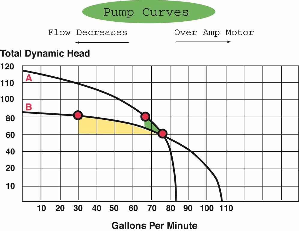
| Figure 1 |
Lots of courses and articles dealing with basic hydraulics have shown us all how to read pump curves and calculate total dynamic head, so I won’t belabor those points here. Suffice it here to say that total dynamic head is the amount of back pressure provided by the circulation system that the pump is forced to overcome in order to provide a certain level of flow.
More important for this discussion is what these pump curves and calculations mean when it comes to real-world applications.
Referring back to Figure 1, you see that both pumps are rated to provide 75 gallons per minute of flow at 60 feet of total dynamic head. We know this because that is the spot on the graph at which the two curves intersect. But the pumps we’re examining are very different: Pump A is considered to be a high-head pump, while Pump B is a medium-head pump.
|
Prime Rate Understanding what makes a pump self-priming will help you in determining optimum equipment locations and in understanding a pump’s limitations. As described in the accompanying text, the process of priming the pump is basically one of evacuating all of the air or condensable gas out of the suction-side lines. Centrifugal pumps of the sort most often used in watershapes are typically not self-priming unless they are specifically designed for that purpose: These specially designed pumps have the ability to remove all the air from the suction-side lines by means and virtue of their volute designs. A self-priming pump has a double volute or priming chamber: When the pump is turned off, the water drains out of the pump and suction lines, but a small portion of the water remains in lower volute area of the pump. This reserved water serves two purposes: First, it keeps the internal seal wet and ensures that the seal faces are wet during the priming process. Second, the water moves to the upper portion of the volute as the impeller rotates, thus purging air out of the pump’s discharge line. What this means in terms of application is that self-priming pumps are useful in situations where they are called upon to lift water above the waterline of the system, typically when they’re installed above the body of water. The self-priming feature is not needed if the pump has a flooded suction line – typical of below-waterline installations. — S.G. |
To understand the practical difference between the two pumps, let’s see what happens when we increase the pressure by 20 feet of total dynamic head (which amounts to about 9 pounds per square inch). According to these performance curves, when you increase the system pressure from 60 feet to 80 feet of total dynamic head, Pump A’s flow decreases to 65 gpm while Pump B’s flow drops to just 30 gpm.
What this means in terms of applications is that Pump A is better suited for systems that experience fluctuations in pressure of the sort that come from using a filter. Likewise, systems that experience high amounts of resistance from in-floor cleaning systems or that have long plumbing runs also would be better served by Pump A.
By contrast, Pump B is the choice for situations in which the pressure does not fluctuate. This would be the pump to choose for application as a spa booster or to drive a waterfall or a vanishing edge: These systems generally do not include filters and for the most part are designed to work at one constant flow rate to maintain a specific, desired effect.
WITHIN LIMITS
Just as helpfully, pump curves also tell us what happens in the event the pump is forced to operate beyond its best efficiency point, as defined by the shaded areas on Figure 1.
If an excess of pressure is put on the pump by increasing total dynamic head, we can see how rapidly the flow decreases to the point where it will actually stop. On the other extreme, we can see what happens when pressure decreases and how rapidly flow accelerates.
|
Cavitation Confusion Perhaps the most common pump problem – and one of the most confusing as well – is cavitation. Cavitation is directly related to a pump-system variable known as “net positive suction head.” If you understand what the variable is all about, it’s easy to see what causes the problem – and how to avoid it. Net positive suction head is divided into two categories: what is required by the pump and what is available. The net positive suction head that is required is a function of pump design, while the net positive suction head that is available is the pressure at the pump’s inlet. The idea is to have net positive suction head available that exceeds the net positive suction head required by the pump. The pump begins to cavitate when the net positive suction head available is less than the required net positive suction head. So what is cavitation and why is it an issue? Technically speaking, it’s the formation of vapor bubbles along the impeller vanes: As the vapor bubbles flow toward the impeller outlet, the increased pressure causes the bubbles to implode – causing the sound that is often described as “rocks jiggling around inside the motor,” a disturbing noise to say the least. Knowing the required net positive suction head isn’t difficult and should be specified by the pump manufacturer; by contrast, knowing the available net positive suction head is a different story – a function of the system’s friction losses, static head or lift and vapor pressure of the water (a given temperature subtracted from the barometric pressure of the system’s elevation – 33.9 feet at sea level). If you have a pump that requires 17 feet of net positive suction head when installed at sea level, the sum of static head or lift, plumbing friction loss and vapor pressure should not exceed 16.9 feet. Of course, isolating those values can be a daunting process, which is why I’d recommend seeking advice and assistance from a manufacturer if you’re not comfortable with hydraulic engineering at this level. — S.G. |
In addition, if we go far to the front of the curve by not having enough resistance, the pump will “overamp” the motor: This means the motor’s rotational rate will increase, thus increasing the wattage, wasting energy and leading to early motor failure. And in both cases, of course, the system is operating outside of the pump’s BEP, which means we would eventually see bearing or pump-seal failure because the radial bearing forces I mentioned above will be out of balance.
The lesson here: Select a pump that matches desired characteristics in terms of pressure fluctuation and that you will ask to operate at its BEP. In this way, understanding pump curves not only helps us choose a pump, but also helps guide us in overall system design.
The characteristics of the system – that is, the environment within which the pump is asked to operate – can be expressed by what is known as a system head curve of the sort I’ve incorporated into Figure 2. This curve dictates how much resistance we will find at a given rate of flow and is developed by crunching several variables in the plumbing design, from pipe size and elevation changes to plumbing turns, jets, special effects and more.
These calculations are a topic unto themselves and well beyond the scope of this article. For our purposes here, the important thing is to understand the relationship between the pump and system curves demonstrated by Figure 2.
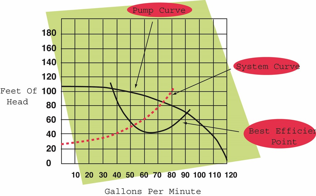
| Figure 2 |
This comparison is an important (but often neglected) part of pump selection, and it’s a step where many system designers run into surprises. Typically, we’ll see that slowing down the water velocity through the system greatly decreases the resistance. In the system shown in Figure 2, for example, we see that slowing the flow down from 80 gpm to 70 gpm decreases the pressure from 100 to 80 feet of total dynamic head.
In practical terms, what you’ll see in many cases is that by decreasing the pump size from, say, 2 horsepower to 1.5 hp, you’ll increase the system’s efficiency by decreasing the flow and the associated total dynamic head. In other words, you’ll find large drops in pressure gained with relatively small decreases in flow. This helps create what many experts refer to as a “hydraulically balanced” system.
More important, this is why, when it comes to selecting pumps, bigger is not necessarily better – and less often quite literally gives you more.
ENERGY TO PERFORM
The bottom line in all of this is that pumps are all designed to perform optimally within certain parameters. The better job you do in matching the pump to the application in terms of pressure and flow requirement, the more reliable and energy efficient the system will be.
There is no such thing as a pump that does it all – there is no high-head, high-flow, general-purpose pump. As a result, it’s important to understand what you’re asking a pump to do and how best to specify one that is suited to meet the demands you’ll place on it.
When you do, the best of all possible scenarios will unfold: Your clients won’t think about the pump at all as they enjoy the watershape that would not function without it.
Steve Gutai is Director of New Product Development, Hydraulics and Heating Systems, at Zodiac Pool Systems, Vista, Calif. He may be reached at [email protected].