


Tank Command


| Surge tanks may end up being out of sight, notes hydraulics expert Steve Gutai, but they should never be out of mind as you strive for efficiency and reliability in setting up water-in-transit systems that call for their use. While proper sizing, selection, placement and plumbing are all relatively simple, he adds, bringing them together in just the right way is crucial when it comes to the success of these dynamic installations. |
In many ways, installing a surge tank is simple. If you get it right, all will be well. As is the case with so many watershape systems, however, getting it wrong can lead to serious problems.
Let’s start with some terminology. Surge tanks are receptacles used to accommodate the surge of displaced water in systems that can be generally defined as water-in-transit or gravity-feed systems. This class of watershapes encompasses vanishing-edge details, perimeter overflow designs, slot-overflow systems and gutter installations and is also frequently used in the design of commercial waterfeatures.
In WaterShapes’ November/December 2002 edition, my friend Skip Phillips wrote an important article about designing water-in-transit systems in general and in particular on the many considerations involved in building troughs that adequately handle the flow over vanishing edges – what he calls “attached” surge capacity.
To complement that discussion here, I’ll be discussing in more detail what Skip calls “detached” surge capacity and the remote tanks that are often used to manage the flow of water in applications where a trough can’t do the job for visual or practical reasons.
THE BASICS
Whatever approach you use to deal with the need for surge capacity, your design must begin with an understanding of water displacement and reflect a clear grasp on what’s involved in plumbing, equipment selection and an array of installation details.
An understanding of displacement starts with the most basic hydraulic unit of all: a cubic foot of water and how it relates to the surface area of a pool, spa, fountain or some other watershape. Familiarity with these quantities and how they work is the key to figuring out how much water will be displaced when a system is on (and its water is in transit) and when it is off (and the water is static).
Let’s visualize that cubic foot of water here:
A vessel holding a cubic foot of water contains exactly 7.48 gallons. This same cubic foot of water can be described as 1728 cubic inches (12 times 12 times 12). In visual terms, this equates to 12 layers that each include 144 cubic inches of water – a fact that makes it easier to visualize the next steps, in which you look at the surface area of a watershape, calculate its area in terms of square feet, convert this surface area into cubic inches, then to cubic feet and, finally, back to gallons (Figure 1).
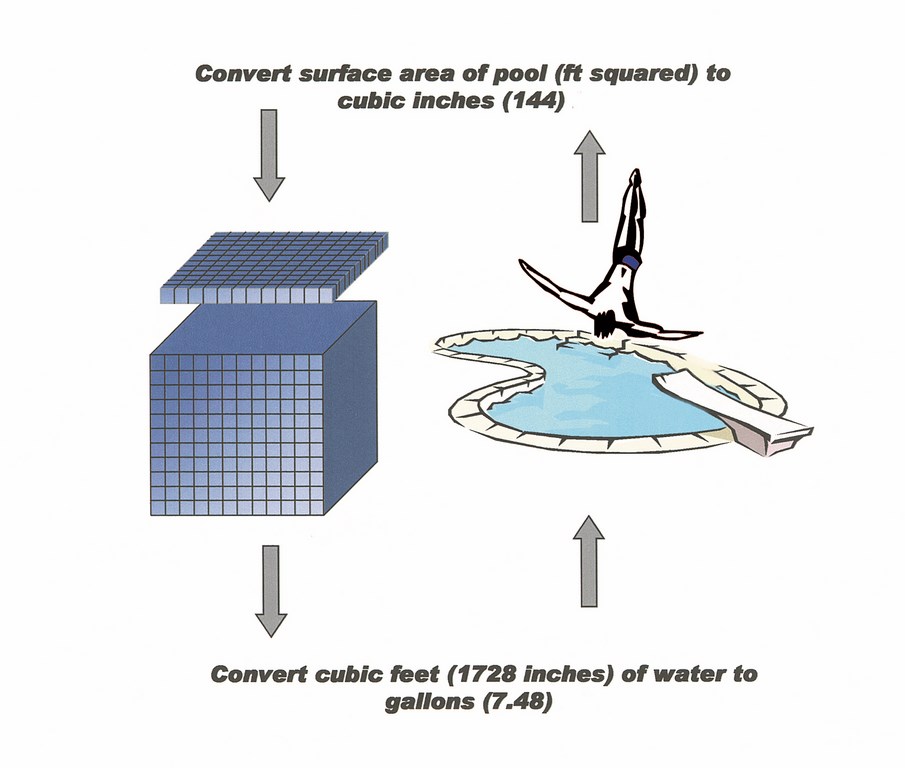
| Figure 1: To visualize displacement, it helps to consider water as layers of cubic-inch volumes that rise and flow over an edge when a bather enters the water – with or without a splash. |
Recall the sliced layers of the cubic foot of water just discussed as you think about the next question: How much water will be displaced?
The two factors influencing the answer to that question are the amount of water being displaced by the pump’s operation and the amount that moves as an unpredictable result of bather surge. Sizing the surge tank to handle the overspill from its weir is easy, but dealing with bather surge can be a real challenge.
Specifications offered by manufacturers of gutter systems for commercial swimming pools provide some guidance, but the scale is generally out of line with the residential systems we see most often. Given that information gap, both Skip Phillips and I recommend a practical approach based on the experience of the country’s leading engineers and builders. As an example, if we have a vanishing-edge pool whose pump discharges a quarter of an inch of water over its edge, the catch basin needs to be able to hold the surface area the pool multiplied by the amount passing over the edge.
As stated above, the surge tank (or catch basin or trough) must hold all the water that flows in normal operation, all the water displaced when the system is off, and all of the additional bather surge. To accommodate all three, Skip and I agree that a properly designed system should be able to accept a minimum of two inches of the surface area of the swimming pool water.
DECISION FACTORS
Sizing a remote surge tank then becomes a simple matter of selecting a container that will hold the required amount of water – and, preferably, somewhat more. Proper selection of the tank, however, does not stop there: You also need to select one with proper construction relative to the ground in which it will be buried.
Surge tanks can be made of several materials – in fact, of any material approved by local building and safety officials. This opens the possibilities to acrylic, fiberglass, stainless steal, polypropylene, cinder block and pre-cast units, so long as the tank is approved for use with potable water (which can be an issue with some polypropylene tanks).
The sole criterion for selection among these tank materials is, as my friend David Tisherman steadily reminds me, the prevailing soil condition and the soil’s reactions to rain, drought, trees and other factors. If the soil is expansive or if trees with invasive roots are nearby, for example, the tank may move periodically or over time. This can cause leaking at the pipe joints and unions and in extreme cases can cause damage to or failure of the tank itself and should lead you to consider only the sturdiest of your options.
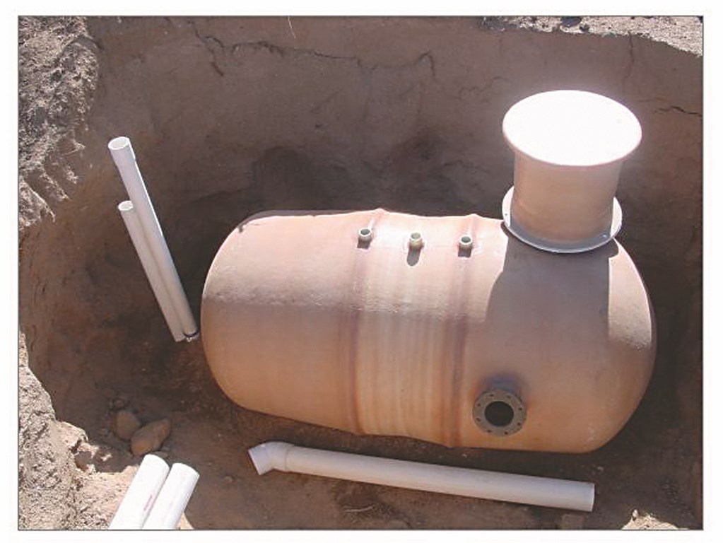
| This surge tank is perfectly suited to application in water-in-transit systems, with plenty of capacity, multiple penetrations to accommodate necessary plumbing and, most important of all for long-term performance, a manhole large enough to allow for easy servicing. (Photo courtesy Creative Water Concepts, Scottsdale, Ariz.) |
Soil acidity is also a key factor: If the pH is low, it can have a corrosive effect that will further limit your choices among tank materials.
There’s no room for guesswork here: You need to know the soil you’re working in and the type of materials and construction techniques best suited to the application. This means you should be talking with local soils and structural engineers, because taking even educated guesses in projects involving surge tanks can result in problems that, in worst-case scenarios, can become catastrophic.
Other factors to consider:
* Surge tanks should be serviceable. This means that any tank you select should have a manhole with a removable cover large enough for an adult to enter.
* Location of the tank is site specific. You need to evaluate space, elevation, slope and accessibility, with the obvious point in mind that these are gravity-feed systems and the tank needs to be placed lower than the source vessel.
The second point in particular has a lot to say about how the tank will be plumbed, a discussion we’ll get to right after we briefly discuss how surge tanks fit into the overall design scheme.
FITTING IN
Generally speaking, there are two approaches used in directing displaced water to a surge tank.
In the first case, the water spills over a weir of some sort in a vanishing-edge, perimeter-overflow or slot-overflow configuration and moves into a gutter system of some kind. The water then flows through the gutter until it reaches the surge tank.
In this setup, the gutter system does not retain water or maintain a specific operating level. The gutter is pitched in such a way that that water moves rapidly to several “pick-up points” (or drains) that send the water via gravity to the surge tank. Open pipes or atrium grates can be used in these gutter systems, in which the surge tank stores the water and acts as the supply vessel for the watershape.
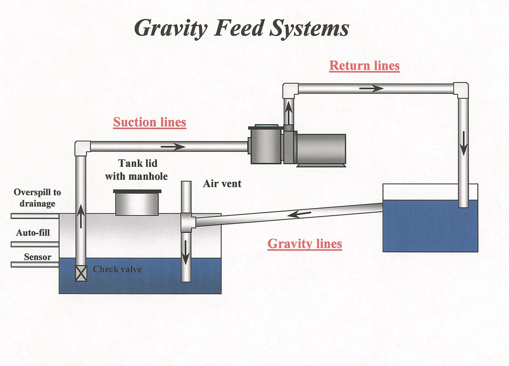
| Figure 2: This schematic shows a simple system in which a catch basin is used to hold the water at a specific level. When that level is exceeded, the overflow moves down the line to a surge tank, driven solely by gravity. |
The second approach is similar to the first – with one significant difference: Here, a catch basin is used to hold the water at a specific level. When that level is exceeded, the overflow moves down the line to a surge tank. This strategy is often used in watershapes in which an attached lower pool or basin is required to run at a certain operating level. Here, the overflow is handled by a standpipe or a modified skimmer that drains water to the surge tank when the level in the basin exceeds the predetermined operating level.
(There is, of course, a third option that involves no surge tank at all: Here, the catch basin is large enough that it can handle all of the displacement, replacing the surge tank with what Skip Phillips refers to in his article as “attached” surge capacity. For this article, however, we’ll stick with systems that use separate tanks.)
With any surge tank in any gravity-feed system, the most important factor to recognize in laying out the system is that the depth of the tank determines everything about its plumbing.
This is true because line sizing for surge tanks is determined by pipe pitch, which controls line velocity and capacity (Table I). Line velocities generally run from two to six feet per second with the pipes pitched an eighth- or quarter-inch per foot. Typically, the lines themselves are made of PVC (schedule 40 or 80) or ABS.
 As their name suggests, gravity-feed lines are not pressurized – but do not underestimate the volume of water they can move! This is why the incoming lines should penetrate the surge tank near the top and the plumbing should be carried down to the floor: This retards water turbulence and significantly reduces the noise caused by water flowing into the tank. (To reduce the gurgling noise associated with gutters as water “circles the drain” in moving toward the remote surge tank, you can vent the gravity-feed lines or use drain covers with snorkels.)
Suction lines will also be taken from the catch basin or surge tank. These lines are pressurized and should be sized to handle the pump’s net positive suction head requirements. A foot valve – including a combination check valve/screen – is a good idea here. The lines should come into the surge tank and be carried down to within a few inches of the floor (Figure 2 above).
UNDER CONTROL
To finish off an efficient surge-tank system, a couple more penetrations are generally needed:
* There should be one for an overflow line tied into the drainage system. (Many auto-leveling systems also include a level-sensing device that triggers a pump if the water level in the tank gets too high.)
* There are also generally penetrations for an auto-fill system, one for the fill line and one for the sensor or probe. This system adds water to the tank if the level drops too low, thus preventing damage to the main system pump. As a rule, the minimum operating level (MOL) in a surge tank should be about one foot.
With another nod to Skip Phillips’ article, it’s important to keep in mind that every water-in-transit system is different. But if you understand the displacement needs of the system you’re creating and meet the basic installation requirements outlined here, you can enjoy full command of these dynamic watershape systems – and transfer that pride and pleasure to your clients.
Steve Gutai is Director of New Product Development, Hydraulics and Heating Systems, at Zodiac Pool Systems, Vista, Calif. He may be reached at [email protected].