


Equating Continuity

As watershapes have become increasingly complex, the need for reliable hydraulic designs that maximize efficiency and reliability is now more pressing than it’s ever been, says hydraulics expert Steve Gutai. With this installment of his ongoing series on hydraulics, he launches a sequence of articles that will explore principles behind the fluid mechanics and hydraulics of custom pools while defining what’s known as the ‘continuity equation.’
Proper hydraulic design is all about asking yourself the right questions.
First are the basic ones: Do you know the flow rate of water moving through the system? Do you know the pressure requirements of each of the components in that system? Can you calculate the system’s flow and pressure drop? Then comes a tough one: Do you know, for the system at hand, how flow and pressure relate to each other?
Knowing the answers to these questions (and weighing the relative importance of each) resides at the heart of a real understanding of hydraulic design. That’s why I’ve broken them out for discussion here, and that’s why we’ll be exploring these issues in great detail in issues to come as we look into a range of interrelated concepts I refer to as the “properties of water.”
What we’ll be building toward is a clearer recognition of the fact that every individual element in a hydraulic design affects the entire design and that success in keeping things in balance in our watershapes requires both a conceptual and a working understanding of what’s behind these key questions.
FLUID MATTERS
The questions encompass concepts that must be understood and applied in a broad and complicated context. To simplify matters for this discussion, we’ll break things down into six distinct topics (the first of which will be covered in this article):
[ ] the fundamentals of flow and velocity[ ] the fundamentals of pressure and head
[ ] a five-step system of hydraulic design
[ ] pump characteristics
[ ] gravity-feed systems
[ ] water flow over weirs.
People in the pool and spa industry have generally seen little value in understanding hydraulics in this detailed way, largely because the relative simplicity of off-the-shelf designs from days gone by created an environment in which precision was not typically required. In other words, even systems that weren’t designed properly worked well enough to avoid much scrutiny for debatable performance.
Today, however, watershape design and construction are much more complicated pursuits. Swimming pools and spas are increasing in complexity because consumers are now asking for much more than they once did. These clients are also more sophisticated, understand their options and place a high value on the contributions pools and spas make to their lifestyles.
They want custom spas, amazing waterfeatures, vanishing edges, slot overflows and interactive waterfeatures – each one of them an outcome that requires both designer and builder to have a firm grip on the basics of fluid mechanics.
In what follows, the focus will be on pools and spas, but the concepts apply just as well to fountains, ponds and streams. Whatever your specialty might be, the goal here is to equip you with information you need to specify and install hydraulic systems that reflect an understanding of what’s really happening.
This isn’t about developing an abstract understanding of scientific principles; rather, it’s about building a practical understanding of design factors that apply specifically to watershapes of the sort we design and build every day.
To understand and communicate effectively on the topic of hydraulic design as it relates to pools and spas, we need to become familiar with key concepts and, as important, get comfortable with a basic vocabulary.
GOING WITH THE FLOW
In all my years of teaching hydraulics at industry events and in schools, it’s clear to me that even though some of these terms – including flow, velocity and pressure as well as related words such as vacuum, head, elevation and friction – are quite familiar, they are not necessarily well understood.
This time out, we’ll focus on the most basic (and crucial) of these elements, that is, flow and velocity, specifically as they relate to pools and spas.
For its part, flow is a term that commonly refers to the capacity of water (in gallons) that a system or component of some sort has the ability to accept within a specified time frame, usually minutes in the case of pools and spas. This value is expressed as gallons per minute (gpm), and common examples of how it is used include main drains rated at 85 gpm, filters rated at 120 gpm, decorative waterfeatures rated at 30 gpm or spa jets rated at 15 gpm.
This flow rate or gpm level is considered to be the maximum flow rate for the component, as specified by the manufacturer. It also refers to the capacity of water that the plumbing network will be able to accept, meaning the pipes, fittings and valves all fall into this set of considerations and must all be considered from the standpoint of gpm relative to the flow through the entire system.
This set of details is about ensuring the compatibility of basic system components: No single component, whether a jet or a filter, should either be overwhelmed or starved or in any other way have its performance negatively influenced (other than by choice) by the flow through the system as a whole.
As important, gpm also refers to the capacity or flow being generated by a pump – for example, you’ll see references to a two-horsepower pump with a specified output of “120 gpm at 60 feet of head.”
Understanding the flow rates of all components used in a watershape system is the first step in designing a swimming pool’s hydraulic system. (It is also useful to note that “gallons per minute” is not the only possible description of flow or capacity: Some systems are denoted in gallons per hour or day, and some are rated in liters per minute, hour or day.)
WATER IN MOTION
The next key term we need to consider is velocity, which is all about the rate at which displaced water moves through a given system.
Commonly measured in feet per second (ft/sec), this velocity figure and the flow rate of the system to which it applies are conceptually attached at the hip. If a two-inch-diameter segment of schedule 40 PVC has water moving through it at 70 gpm, the average velocity of that water is 6.7 feet per second, meaning the system would have a line velocity of “6.7 ft/sec.”
In reality, the term average velocity is more accurate but less widely used. Sticklers for terminology prefer it because it more completely describes the velocity of the water within a pipe of a specific size: The actual velocity is higher the further away the flow is from the pipe wall, so an “average” is what is truly being described.
This more-accurate term will become important as we move further into this discussion: The drag on flow created by the pipe wall reduce the velocity of the water, which is why it is conceptually valuable to wrap our minds around “average velocity” as we approach calculations of a system’s loss of velocity as a result of friction.
I emphasize all of this because there’s a critical relationship between the flow in gpm, the velocity in ft/sec and the inside area (or flow section) of a pipe. This relationship can be described by using the continuity equation.
The continuity equation states that the flow is equal to the inside area of a pipe multiplied by the velocity. Another way of saying the same thing is that the velocity is equal to the flow divided by the flow section of a pipe. However you look at it, if you shrink down the pipe size or flow area, the flow in gallons per minute stays the same but the velocity in feet per second increases.
To understand this in more direct terms, let’s return to our two-inch piece of schedule 40 PVC pipe and assume a flow source (in this case a pump) is generating 70 gpm. What happens to the line velocity and the flow if a smaller size pipe, such as 1-1/2-inch schedule 40 PVC, is used downstream?
INSIDE THE SYSTEM
To find out, let’s say we have a long pipe run of 100 feet: The first 50 feet of the run is 2-inch schedule 40 PVC that transitions to 1-1/2-inch schedule 40 PVC pipe for the second 50 feet.
Figure 1 illustrates this situation: When the water travels from point A1 to point A2, the flow remains the same. At A1, the flow section of the pipe is 3.14 square inches with a line velocity (V1) of 6.69 feet per second. At A2, the flow section shrinks to 1.77 square inches while the line velocity (V2) increases to 11.03 feet per second.
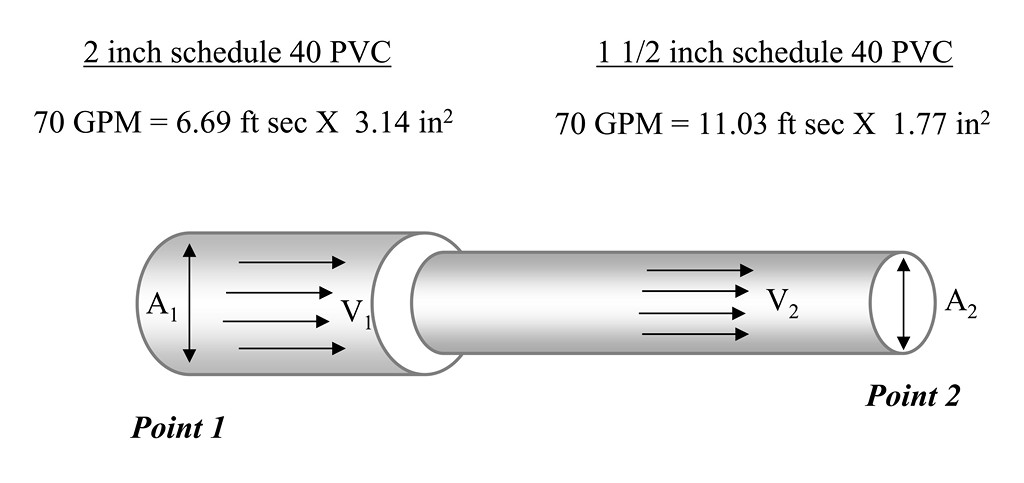
| Figure 1: This schematic illustrates the key point that in a line where the flow remains constant, the line velocity increases if the pipe size is reduced. In this system the flow is equal to the line velocity multiplied by the inside area of the pipe – that is, flow (gpm) = A1 x V1 = A2 x V2. |
This change perfectly illustrates the significance of the continuity equation as it applies to hydraulic design for watershapes: It indicates that the area times the velocity is the same. In other words, because the flow remains constant, when the pipe size or flow section is reduced, the line velocity is increased.
It’s important to note that the rate of flow in all sections of the piping is the same in a single inlet/outlet system of the sort seen in Figure 2 – but that this will change when the system expands and we start considering plumbing networks, loops and manifolds.
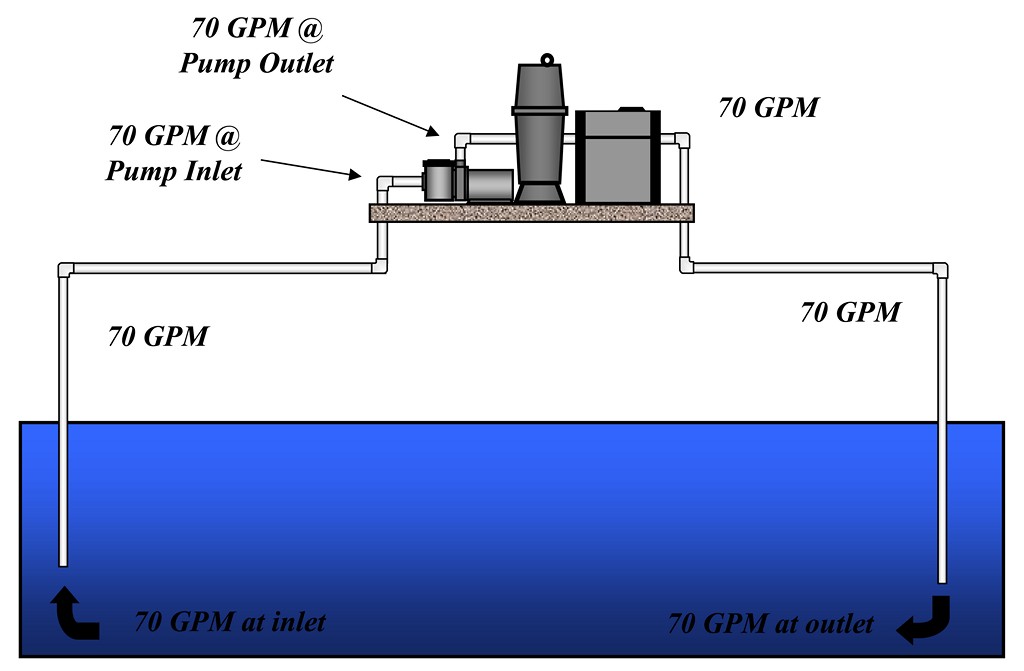
| Figure 2: This schematic shows a simple system in which the flow is constant at 70 gpm at all points – a consistency that disappears and a system that becomes much more complicated once it expands to accommodate various plumbing manifolds, loops and networks. |
It’s also important to recognize that the continuity equation is also a foundation for understanding component compatibility. All components used in a pool’s hydraulic system – main drain grates, spa jets, filters, waterfeatures and more – have their assigned flow rates. It is important for system performance that all equipment be sized properly and that their flow rates correspond. (Conversely, the continuity equation helps us understand component failure in situations where mismatched flow rates occur.)
Understanding the relationships defined by the continuity equation is extremely important because it gives us direct insights into pressure drops within a watershape’s hydraulic system. Simply put, this is the all-important key that unlocks the door to more effective system design and installation.
PRACTICAL APPLICATION
Figure 2 shows flow in a system in its simplest form, assuming, first, that all readers of this article understand that a suction-side line for a watershape would include skimmers, drains or gravity-feed outlets that provide flow to the influent side of the pump; and that the discharge side of the pumping system might include various inlets – return fittings, spa jets, in-floor returns, fountains and more.
The continuity equation should be considered while looking at the entire branch of plumbing, the totality of active inlets and outlets on both the suction and discharge sides of the pumping system. This gives you the ability to design a hydraulic system using line velocity as a main criterion – something that has not historically been the case (at least in the pool and spa industry).
Keep in mind that hydraulics is one of those subjects that may seem simple in the explaining, but becomes far more challenging when applied in the field. So that’s all for now: My intention is to keep these articles brief so their concepts can be internalized more easily. In articles to come, we’ll build on this foundation as we work toward clearing away the mysteries of hydraulic-system development, step by step.
Next: The continuity equation will be even more critical when we explore a new set of conceptual building blocks – head and pressure.
Steve Gutai is Director of New Product Development, Hydraulics and Heating Systems, at Zodiac Pool Systems, Vista, Calif. He may be reached at [email protected].