Water Under Pressure

Of all the concepts of hydraulic-system design, there are few that have more importance than the correlation between water flow (that is, capacity expressed as gallons per minute) and line velocity (the speed at which the water travels).
As water travels through a pipe, its increase in speed (that is, its line velocity) results in an increase in resistance (expressed as feet of head) and in a reduction of end pressure, which is measured in pounds per square inch (psi). In other words, an increase in friction losses and a drop in pressure is the result of increased water velocity at a given flow.
If that makes sense to you without further explanation, then you know much of what you need to know when it comes to selecting pipes and fittings and setting up a watershape’s plumbing system. If it doesn’t, this article will cover the basics – from selecting pipes and sizing lines to plumbing in downsized manifolds and setting up loops – all with a goal of designing plumbing networks with even flows and pressures.
But before we begin, we need to recognize that discharge lines are not sized the same way as are suction lines. In other words, there are two sets of calculations you must develop for each watershape’s plumbing system. This time, we’ll cover only the discharge side of the system – that is, the plumbing immediately downstream from the pump.
FROM PUMP TO POOL
An important point to recognize from the outset is that there is generally a right way to plumb any given watershape. There is a correct pipe size, there are proper fittings, there is a right pump size, and it’s all a matter of thinking things through and making the right choices.
A good place to start is with the piping itself. You’re probably most familiar with schedule 40 PVC piping, but it’s likely you’ve also had some exposure to schedule 80 PVC as well as CPVC and different grades of copper piping and perhaps even steel piping.
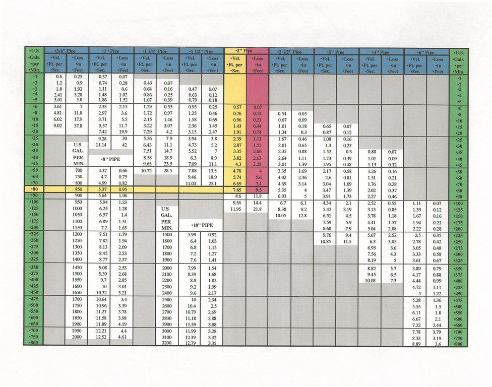
| Figure 1: A friction/flow chart for Schedule 40 rigid PVC pipe, indicating friction loss of water in feet per 100-foot lengths of pipe. |
The most common material for residential pool plumbing is schedule 40 PVC. For the most part, you don’t get into other piping materials unless you are involved in commercial work, where the distinctions have mostly to do with a given material’s ability to handle heat, its durability and its cost.
The main point here is that each of these materials has its own friction flow chart, reflecting the fact that each creates resistance to flow at different levels. Once you choose a material, you can choose the water’s velocity – a key bit of information you need to size up a plumbing network.
The Hydraulic Institute’s and the National Spa & Pool Institute’s standards for maximum line velocity in schedule 40 pipe are set at 10 feet per second (fps) on the discharge side, 8 fps on the suction side. If you select pipe and fittings that do not operate to these parameters, the result will be a system with reduced efficiency.
Using a friction flow chart (Figure 1 above), you find a set flow in gpm at a specific water velocity, with the friction loss expressed in feet of head or the pressure loss that results. Once the flow requirements are set, the water velocity is the determining criterion. So using the chart and focusing on the discharge side of the system, we can set our velocity at 6 fps – a reasonable spot below the maximum allowable velocity and a common target for pool plumbing.
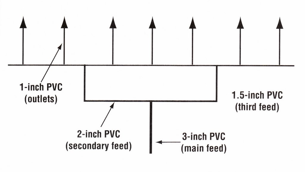
Referring to the chart, 3-inch schedule 40 PVC will yield 140 gpm at 6 fps. This is the main feed line into the manifold shown in the schematic (Figure 2 below). Now we take the 3-inch line and split the flow in half to determine the next pipe size. If we do this, we have 70 gpm, which steps us down to 2-inch pipe, which, according to the chart, lets 70 gpm flow at about 6 fps.
| Figure 2: Basic manifold plumbing, in accordance with the friction/flow chart information found in Figure 1. |
At this transition, we should use a 3-inch tee fitting, because dropping all the way down to a 2-inch tee would cause unnecessary resistance. Further down the line, we split the 2-inch line, cutting the 70 gpm flow in half, and resize the pipe according to the desire 6-fps flow. This gives us 1.5-inch pipe that allows for a potential flow of 40 gpm at 6 fps. At this transition, we should use a 2-inch tee.
At the next tee fitting, we split the flow in half again to 20 gpm with a 1.5-inch tee and reduce the pipe size to 1 inch at 6 fps. From pump to pool, we used pipe sizes and tees that maintained the flow at a constant 6 fps.
REDUCTIONS
There a key message that comes through in the discussion just above: All transitional fittings and tees should be from the larger pipe size and down to the next pipe size.
With a 3-inch tee, for example, the branch side accommodates a 3-inch pipe, while the through sides of the tee are reduced with bushings down to 2 inches each. This simple approach takes much of the guesswork out of fitting selection and reflects the fact that using water velocity as the deciding criterion keeps pointing us in the right direction toward a plumbing system that has even water flow and avoids the accumulation of resistance or loss of pressure.
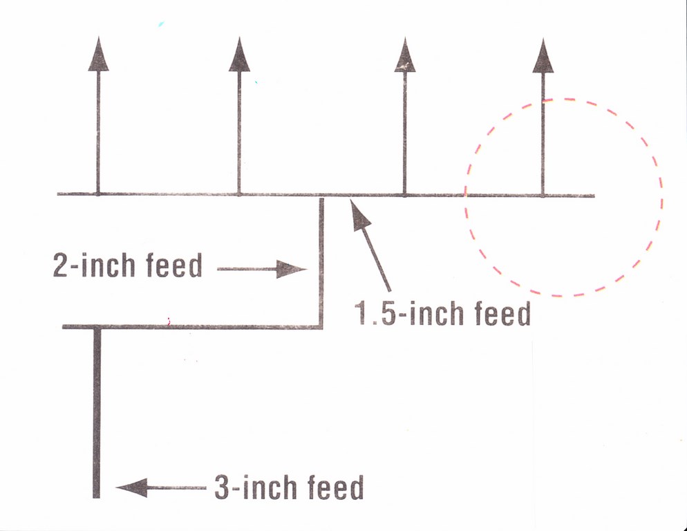
| Figure 3: In a basic manifold system, you can help even out the flow and pressure by adding an additional 6 to 12 inches of pipe at the manifold’s end (see the highlighted area of the schematic) instead of completing it with a 90-degree elbow leading to an outlet. |
The key to setting up this sort of even, balanced discharge piping is keeping the water velocity at a constant level of 6 fps – and the same basics apply whether you want the flow at 6 or 8 or 10 fps.
Beyond these simple piping selection and sizing principles, there are two special piping configurations that can help you to even out a system’s flow and pressure.
One is the use of an additional tee fitting at the end of a manifold run at a point 6 to 12 inches past the last feed line (Figure 3 above). If this is done instead of using a 90-degree elbow to terminate a run, the flow at the manifold’s end will be more consistent with the flow found at other discharge points.
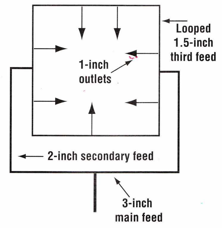
The other velocity-leveling approach has to do with setting up plumbing loops in which the last branch of piping before the water discharges is tied together (Figure 4). As a rule, I’d suggest looping plumbing whenever possible. With this configuration, the water flow and pressure become very even at all discharge points, and it all works in accordance with the basic manifold-downsizing plan just discussed – but with one difference.
| Figure 4: Using a looped feed line just before the outlets is almost always a good idea because it helps to create even flow and pressure. |
As shown in Figure 4, the last feed before our discharge points is where the pipe should be tied together to create a loop. The water’s flow and pressure will equalize as a result of the ends being tied together.
This looping technique works especially well for discharge lines used for spa jets, fountains, in-floor cleaners or any application in which the water is discharged in a vertical column or where you want even flow and pressure from all points of discharge.
Next, a look at the suction side of the system.
Steve Gutai is Director of New Product Development, Hydraulics and Heating Systems, at Zodiac Pool Systems, Vista, Calif. He may be reached at steve.gutai@zodiac.com.


