


The Science of Lighting


As I see it, successful landscape lighting is a two-part process: First, the designer applies aesthetic principles that create the art, then he or she supports that artistic vision with scientific and technological savvy. One without the other doesn’t work: You can’t effectively practice the art until you’ve mastered the science.
In my 17 years as a lighting designer, I’ve encountered lots of professionals who have the artistic part of the equation down pat but fall well short when it comes to working with electricity. The plain fact is, you can use the best fixtures in the world and understand the aesthetic issues like the back of your hand, but if you can’t consistently deliver power to those fixtures at correct, reliable voltages, the overall system will not perform properly and has the potential to become a maintenance nightmare.
There’s no way a single article can bring anyone up to speed with all of the issues involved in the science lighting. Instead, my intention here is to introduce watershapers to a basic, commonsense approach to laying out low-voltage, halogen lighting systems, the goal being to enable you to converse intelligently and persuasively with lighting designers in the interest of helping your clients obtain systems that not only look good, but also function properly.
PROPER FUNCTION
Just as is the case with watershapers, there’s a definite need for taking care in selecting a lighting designer. These days, in fact, a big part of my business involves fixing systems that don’t deliver the requisite 11 to 12 volts of electricity to each of their low-voltage halogen fixtures. (And it’s fair to say that most systems these days use halogen technology: Since arriving on the scene some 20 years ago, these lamps and fixtures have both revolutionized and come to dominate landscape lighting.)
Time and again, I’m called in to evaluate systems installed by someone who may have had the right ideas when it came to making a setting look good but who simply lacked the necessary understanding of basic electrical concepts and made the client compensate for that deficit by paying for frequent, expensive lamp replacements in systems generally inclined to breakdowns.
Overcoming these long-term maintenance concerns is why I’m such a stickler when it comes to defining and achieving proper voltage levels: I know that if a system operates outside the recommended voltage tolerances (a common feature of improperly designed systems), fixtures won’t function correctly and will either be too dim or burn too hot.

| In the field, I start the layout process by placing flags where I want lighting fixtures to go, then work my way back through each branching series and home run in the system to ensure each group of fixtures will be adequately served with respect to power delivery. |
If the voltage reaching a halogen lamp is too low, the tungsten gas in the lamp won’t deposit properly on the filament: The desired “halogen effect” therefore cannot occur and the light output will be significantly dimmed. Conversely, if the voltage is too high, the lamps will burn too brightly and the desired visual effects will be distorted by hot spots. Moreover, when lights don’t operate at the proper voltages – high or low – they don’t last as long as they should. These early burnouts frustrate clients, which is one of the main reasons I receive calls to work on existing systems.
The picture is somewhat complicated by the fact that halogen lamps are available for operation over a range of voltages, with 12, and 120-volt units being the most common. To me, the lowest-voltage (12-volt) option is the best (and safest) option: When installed in properly designed systems, these lamps offer tremendous output relative to energy consumption and will last a long, long time.
The specification sheets for most of these 12-volt halogen lamps say that 10.8 volts are needed to generate enough heat to create and perpetuate the halogen effect. When input falls below that level, these lights can’t work as designed – it’s as simple as that.
But as I see it, one of the keys working successfully with halogen lamps is to stop thinking about them as individual components and instead to see than as links in systems of variable lengths, with electrical balance within any given system being the goal.
WORKING TOWARD BALANCE
It’s not a perfect analogy, but you might find it useful as watershapers to think of lighting systems as being similar in some ways to hydraulic systems: Where every jet in a spa has a recommended operating tolerance relative to flow and pressure and a balanced hydraulic system is one that creates a condition where all jets in the system operate within the proper range, the same generally holds true for lighting systems: You want to create a system where every fixture operates within its specified range.
Those who don’t understand the need for this balance often (and unwittingly) design systems where one lamp might be receiving 9 volts and another receiving 13 or more. You don’t have to be an electrical engineer to get the point that, under those conditions, some lights will be dim while others will burn too hot and prematurely fail. To avoid these problems, I make certain that every fixture in a cluster of lights operates within a half volt of the others within the 11-to-12-volt range.
This objective puts a tremendous amount of pressure on the system-design process and the way I lay out my systems.
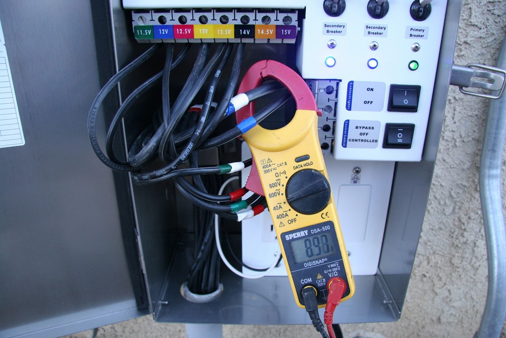
| I am a firm believer in checking and rechecking voltage outputs and amperage draws at the transformer: As I see it, a multimeter is to a low voltage landscape lighter what a stethoscope to a doctor: It’s the only way I’ve found to be assured that lamps in the system are getting power at the proper level. Notice that all cables are color coded for easy identification in the field. |
In my view, the best place to start is with the power feed (or “home run”), which is the wire that delivers power from the transformer to the fixtures. Just as with water and pressure in hydraulic systems, as electricity flows over a length of wire, voltage drops or attenuates because of resistance it meets along the way. Therefore, I lay out my systems so that these home runs feed small clusters of lights situated no more than several feet apart from each other.
My systems are all arranged so that the home run connects to a fixture that acts as a hub, with all other fixtures on that circuit wired to either side of the hub in what’s referred to as the “T method.” A common (and incorrect) alternative to this is the series (“daisy chain”) approach in which the home run feeds a single fixture; wires then pass in sequence to a succession of other fixtures along the line. Using this option, fixtures at the end of the line will inevitably receive less voltage than the one wired directly to the home run.
I group my systems in sets of three to five fixtures with lines branching off of the hub because this arrangement helps me equalize the voltage at each fixture. I also take a conservative approach to the standard manufacturer recommendation that there should be no more than 25 feet of wire between the home run and the last fixture on a given side of the hub. In fact, I seldom come anywhere close to pressing that limit: If a layout has me putting a fixture any more than 15 feet away from the home run, I’ll use a separate home run for that fixture.
Yes, this often means my systems become quite complicated in a schematic sense, but it’s the only way I’ve found to deliver the desired, fully balanced results my clients crave.
WIRED UP
After appropriate layout, the next key to good system design has to do with the wires chosen to get the job done.
There are several schools of thought on this, but experience has taught me to stick with 12-gauge wire – and this is despite the fact that many manufacturers pre-install 16-gauge wires with their fixtures as 25-foot leads ready for connection to the home run. As I see it, 16-gauge wire leads to a high level of voltage drop that I can avoid by using 12-gauge wire with runs of a more conservative length.
Without delving deep into electrical theory, lamp wattage is another factor here. Most low-voltage lamps operate at between 20 and 50 watts, with higher wattage meaning brighter light and greater resistance (and voltage drop) at that fixture. Using this consideration to my advantage, I always connect my home run to the fixture operating at the highest wattage.
| I typically install the home run of cable directly to the ‘middle’ fixture in any given grouping. I test the voltage at the home run to determine the power terminal on the transformer to which I will be connecting that particular wire to achieve an optimal power level of 11.4 to 11.8 volts. As long as my other fixtures are relatively close to this power connection, there’s no need to take readings at the other fixtures. |
If, for example, I have a cluster with four fixtures, two operating at 35 watts and two at 20 watts, I’ll establish the hub at one of the 35-watt fixtures. Then I’ll run one wire to the other 35-watt fixture and the other to one of the 20-watt fixtures and then the next 20-watt fixture, thus balancing the voltage drop to the greatest degree possible for that set of fixtures, with 35 watts on one side of the hub and 40 on the other.
Again, distance is extremely important: If, using the example just described, the 35-watt fixtures are just five feet apart and the hub fixture is operating at 11.5 volts, you’ll probably only lose about two-tenths of a volt between those fixtures – well within the target operating range. When the distance is greater and I see a voltage drop of, say, half a volt or more, I’ll sidestep any potential problems by establishing a separate home run.
As far as installation is concerned, I depart from some other lighting experts in that I don’t typically use junction boxes to create hubs. Instead, I’ll wire the home run directly to the fixture itself. I do so because, through the years, I’ve found that the added crimp connections where the 25 feet of 16-gauge wire transitions to the 18-gauge socket wire sometimes come apart; moreover, junction boxes themselves can be hard to find later on, especially if the landscape has subsequently been altered in some way.
TRANSFORMED REALITY
The next key to creating an effective, satisfying lighting system has to do with knowing the capabilities and limitations of the transformers you’re using.
These days, most commercially available low-voltage lighting systems use multi-tap transformers. These units have multiple ports or taps that connect at different voltage levels, commonly as 11- to 15-volt outputs in single-volt increments. Connecting home runs to the different taps enables you compensate for voltage losses experienced with a given line.
The problem with transformers, however, is that they’re not all created equal. Let’s say, for illustration, that you have two identical systems wired to transformers that have the same nominal outputs but come from different manufacturers. Experience tells me that one might deliver the exact specified voltage, but the other could be off by a volt or even more. That’s a huge difference with the sort of sensitive systems we’re dealing with: If you’re not aware of the idiosyncrasies of the transformer, you can do everything right and still end up with an out-of-balance system because you don’t know the actual voltage you’re delivering to the hub.
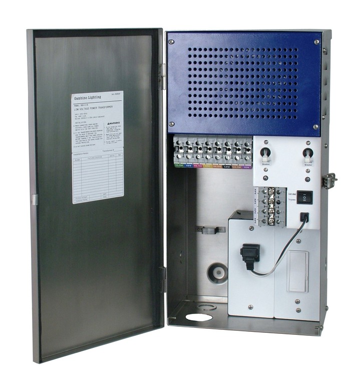
| This transformer unit is typical of those I use in my projects. It’s a custom style I’ve worked out with one of my suppliers and has the advantage of allowing me to adjust voltages at 0.5 volt increments – a big edge when it comes to setting up groups of lamps so they all receive power within the target range. In addition, this unit features magnetic primary and secondary circuit protection, bypass of control modules for service, a manual override, LED indicator lights and enough room to hold three control devices, such as a timer, a photocell and a dimmer switch. |
The reason for this supplier-to-supplier variability is the fact that there are no standards for how transformers should react once loads are placed on them. Each vendor chooses which size of wire to use in their cores and coils, for example, and each one chooses a system configuration. In addition, when transformers are checked on the assembly line, they are tested unloaded for proper output despite the fact that a load will change output to differing degrees.
Some might argue the point with me, but this variability in performance has led me to ignore the charts that accompany transformers. Instead, the only way to get predictable results is to mock systems up and check outputs with a volt meter: Only then can you be absolutely sure of the voltage level you’re delivering to the hub.
In my own practice, I’ve become so obsessed with controlling transformer outputs that I now work with a vendor that makes me units featuring taps at half-volt increments – that is, 11.5, 12, 12.5, 13 and 13.5 volts on up to 15 volts. This enables me to create extremely precise voltage levels for various lighting clusters while staying within the 11-to-12-volt operating range with each of my fixtures.
This can be done with single-volt-interval transformers, but I’ve found this fine-tuning enhancement to be most helpful, especially when you have 11.2 volts at the hub: This will result in less than 11 volts being delivered to downstream fixtures, but moving up to the next-higher tap will leave you with an unacceptable 12.2 volts at the hub. With 0.5-volt increments, however, 11.7 volts is just right.
The other big variable with transformers is simply how many cables you can connect to them. The units I use have super-sized terminals to which I can attach up to eight 12-gauge cables per common tap (of which I have two per 25-amp circuit), thus giving me the capability of connecting 16 cables. Some units have smaller terminals that handle just three cables – a capacity factor that plays a large role in system design.
Also, there are big differences in quality with respect to the connections themselves: Some transformers, for example, enable to you to make internal connections, while others (generally on the low end) have only external terminals that will be exposed to the elements and other potential types of damage.
AT THE SOURCE
Moving even farther back along the electrical chain of things, it’s important to ensure that the transformers in any given system aren’t overloading the breakers on a home’s electrical service panel. A 120-volt circuit will support a total of 2,400 watts, but it is best never to load them with more than 80 percent of that capacity, meaning you can predictably draw approximately 1,800 watts from any single 120-amp circuit.
On small projects, for example, if you have a dedicated breaker for the lighting system, a single circuit often does the trick as it takes many 20- to 50-watt fixtures to exceed the 1,800-watt level. Obviously, however, if you have a large system with hundreds of fixtures, you need to be aware of circuit capacity and make provision to tap into multiple breakers.
Some lighting specialists get themselves into trouble when their systems share a circuit with other systems – pool equipment, for example. The other system might demand a lion’s share of the circuit’s available wattage – so much so that when everything is operating, the load will exceed capacity and the circuit breaker will overheat and cut off all power.
The best situation is one in which the lighting has its own circuit. Failing that, you need to know the peak draw of other devices on the line and plan accordingly.

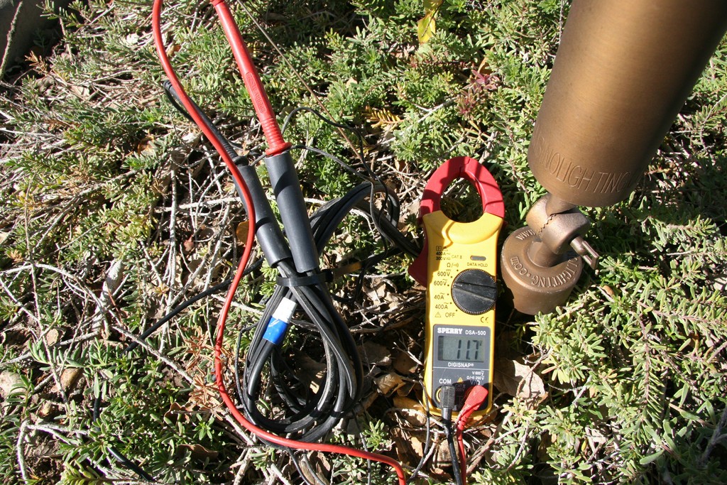
| The length of a wire run in a lighting system makes a big difference in performance because of voltage drop. In this case, for example, the need to bury the cable along meandering contours added to the length of the wire needed to create the home run – not necessarily a huge factor, but enough of one that it required me to recheck voltages once everything was in place. |
In addition, you need to consider available amperage. As a rule, I prefer tapping into 120-volt circuits that operate at 20 rather than 15 amps. The reason for this is straightforward: A 15-amp circuit is wired with 14-gauge wire and creates a greater voltage drop on the 120-volt or primary side than does the 12-gauge wire used with 20-amp circuits. That’s important and cues us into the fact that we need to consider the voltage drop on the 120-volt side of the system – that is, losses before the power ever reaches the transformer.
In systems where you can locate the transformers relatively close to the service panel (as is often the case with new construction), this sort of voltage drop isn’t likely to be much of an issue. But where you’re adding lights to an existing property, the transformers might be set at some distance from the service panel, making it imperative for you to factor in the voltage drop and design your system accordingly.
Again, these electrical-system concepts are roughly analogous to hydraulic systems and the flow, pressure and resistance found in water lines: You can only divide the flow up based on what’s available. Thus, a 12-guage wire connected to a 20-amp, 120-volt circuit only a few feet or inches away from the source delivers more capacity than does one where the electricity is flowing over a longer run before it reaches the transformer.
PRACTICAL TERMS
When you break all of this down and look at the lighting process as a methodical set of key steps, it all begins to make sense. Just as with hydraulics, it’s a case of science and art going hand in hand: If you want to achieve the desired results, you need to know what’s involved in both. In my case – and in a basic approach I suspect is used by watershapers as well – I start by designing projects in aesthetic terms, then double back and lay out the electrical system to accommodate the results I’m trying to achieve.
Once the artistic game plan is in place, I flag the entire system, locating each fixture so I can see the length of the wire runs and determine the loads within the system. Then I break the system up into clusters based on the layout.
|
How Low is ‘Low’? What do we mean when we say “low voltage”? These days, there are two schools of thought: To some, low voltage means anything lower than 30 volts (as in the National Electric Code) despite the fact that the Underwriters Laboratories (UL) won’t approve transformers operating at levels greater than 15 volts. Indeed, some manufacturers still produce systems that operate at higher voltages, but I’m in the other camp, which means I believe that low voltage refers to systems that operate at UL-approved levels of 15 volts or lower. The biggest problem I see with systems that operate above 15 volts is that, when a light or two burns out, the voltage levels at the other fixtures rise dramatically and will burn out remaining lamps in rapid order. (This happens because a burnt-out lamp offers no resistance in the line, so voltage levels rise for other lamps on the circuit.) When more lamps burn out, the problems multiply and you have a domino effect that will harm every lamp on a particular line. (This is a particular problem on circuits connected to taps of higher than 15 volts. Another issue, of course, is inspections: Although such checks are rare, landscape lighting systems are sometimes scrutinized and you can run into problems for using equipment that lacks UL approval. — M.G. |
To illustrate, let’s consider a large property that requires 120 fixtures and 10 multi-tap transformers. That’s intimidating on its face, but if you break it all down and look at it as a series of vignettes, it’s relatively easy to balance the loads on each home run. In other words, a big system is really just a combination of smaller, more manageable parts.
Before I get that far, however, I ascertain the balance on the 120-volt side (that is, from the circuit breaker on the service panel to the transformer) and on the low-voltage side (from the transformer to the hub and the fixtures on that line). The more transformers you add to a 120-volt line or the more fixtures to a single hub, the greater the voltage drop. Thus, what you’re really doing is considering the voltage for each grouping of lights all the way from the service panel and through the transformer to the fixtures themselves.
This may all seem terribly complicated, but experience helps – and there’s no substitute for starting off with the right way of looking at these systems on a scientific basis. But where I get the impression that working with all but the most complicated hydraulic systems can be a matter of some approximation on the part of a watershaper, my work as a designer of electrical systems calls for a precision that can’t be left to habit, supposition or chance.
This is why, when I hook up a system, I’ll bury all the connections to the fixtures except for the fixture linked to the home run: This is where I do final checks on voltage levels.
Generally, I start by connecting everything to the 12-volt outputs on the transformers, having color-coded every wire so I can keep track of which clusters I’m testing. If I test the blue wire, for example, and it reads 10 volts at the home run fixture, I know that I need to move that one from the 12-volt to the 14-volt tap to bump it up by two volts. If the yellow wire tests at 10.5 volts at the hub, I’ll move it from the 12-volt to the 13-volt terminal to move it into the desired range.
CAREFUL CONSIDERATIONS
Make no mistake: This testing process is absolutely critical. If I test a system and can’t bring the voltages within the desired range by adjusting the connections at the transformer, then I need to reconfigure layouts so that each home run operates within the target range.

| There’s a simple reason why I want my lighting systems to perform to the best of their technological capability for as long an operating life as possible: When things get this complex, maintenance becomes a huge issue. No client will be satisfied if there’s a regular need to have someone scamper over the rocks to keep things looking their best. |
This is why the half-volt increments on my custom transformers come in handy: With this flexibility, I can almost always hit my targets without having to go back to the drawing board.
While I suspect some of you out there will want to take this information and apply it yourselves, as I mentioned at the outset, that’s not my goal here. Ultimately, what I’m hoping to foster is your increased awareness of the issues involved in good lighting design and give you a working vocabulary that will let you speak with lighting contractors on an informed basis and be better advocates for your clients.
Indeed, creating perfectly balanced systems takes experience and a polished, educated, experienced understanding of how all the electrical factors involved in lighting-system design work together. As with many endeavors, there’s a broad range of quality with respect to available products and the expertise of the designer or installer, so being informed is your best assurance of obtaining good results.
As I think you can tell, my own approach involves leaving little (if anything) to chance and doing all I can to apply my knowledge and experience to deliver great results. Ultimately, you need some of this sort of understanding to serve the best interests of your clients and make certain they’re happy when the switches are thrown and the lights bring your nighttime settings to life.
Mike Gambino owns and operates Gambino Landscape Lighting in Simi Valley, Calif. A graduate of Adelphi University with a bachelor’s degree in business administration, he has been a California-licensed landscape contractor since 1990. In 1995, he began specializing in high-performance low-voltage landscape lighting systems designed and built to last. For more information, visit his web site: www.gambinolighting.com.