


Speaking the Language

As is true of many business sectors, the architecture, engineering and construction industry (commonly and conveniently abbreviated as A/E/C) has its own language – and the construction documents generated by those professionals (watershapers very definitely included) are the medium through which everyone communicates.
The challenge for watershapers is that we’ve come to the table a bit later than most other members of the A/E/C community, so we have some catching up to do. Fortunately, the National CAD Standards I’ve been writing about during the past year or so (in the December 2007, May 2008 and August 2008 issues of WaterShapes) offer strong support to those needing to get up to speed.
This time out – the last part of my coverage of the ABCs of the NCS – I’ll provide you with an overview of a cluster of modules (Terms and Abbreviations, Symbols, Notations and, finally, Code Conventions) that are all about a common language that, when applied, not only helps watershapers work with other project professionals but also assists in communications about regulatory information with “authorities having jurisdiction” (AHJ) over the project.
As I’ve stressed repeatedly throughout this series, the concepts presented in the NCS are not limited in utility to those who work primarily or exclusively with computer-assisted design (CAD) systems. Even hand-drafters, after all, need to speak the same language as their colleagues!
COMING TO TERMS
When I first read the table of contents in the NCS, I found myself thinking “Why do they need 178 pages for terms and abbreviations?” Even considering the number of possible alternative abbreviations, that total represents almost 20 percent of the overall page count and seemed a bit of overkill.
The plain fact, however, is that there are lots of duplicate or overlapping terms and abbreviations already in common use. The mission the NCS undertook was to boil all of the possibilities down to officially accepted usages that work and can be applied by all of the disparate functions contained within the vast A/E/C industry.
In running through the list, I encountered a few persistent duplications. ALT, for example, can refer to “alternative” or “altitude,” with the correct meaning dictated by context. In another case, context was obviously the key: COP is used for both “coping” and “coefficient of performance” (a heating term): I don’t think anyone looking at a set of plans would ever be confused enough to think that a term directed at a watershape’s perimeter material would be the heating term.
Many of the abbreviations are acronyms that shorten common references into more convenient units. Some of these, at least the first time around, will need some clarification as you review construction documents. For example, if “OF/CI” is pointing to the coping, competing contractors need to know what the abbreviation means if they want to place a proper bid on the job.
If the construction documents themselves don’t carry a list of abbreviations (most do as a matter of convenience), those bidding contractors risk both low- or high-bid problems if they don’t know that OF/CI means “owner furnished/contractor installed.” In my practice, our plans include tables of these terms, including a number we’ve made up for specific watershaping terms not defined by the NCS – including SKM, which we use to denote skimmers.
A particularly interesting section of the terms and abbreviations module is a list of what the NCS calls “preferred terms.” Helpfully, this one is organized alphabetically by non-preferred term, so you’re quickly guided to the right one instead of having to hunt for something unfamiliar.
A few notable ones are of interest to watershapers: We are asked, for instance, to use “gage” instead of “gauge,” “GFCI” instead of “GFI,” “cast-in-place” instead of “poured-in-place,” and “reinforcing” – that is, REINF – instead of either “reinforcement” or “reinforcing bar.” None of these abbreviations use any sort of punctuation (no apostrophes, periods or other symbols) and are rendered exclusively in all-capital letters.
Interesting, the NCS doesn’t particularly encourage the use of these abbreviations but recognizes that space and time are issues and that shortened forms of reference can be useful – so long as the usages are consistent, clearly understood or, where terms of abbreviations are unfamiliar, clearly defined in the construction documents themselves.
HIEROGLYPHICS
While the Terms and Abbreviations module addresses written language, the Symbols section defines a standard graphical language consisting of about 1,500 examples. These symbols represent objects, materials, finishes or general information (bar scales, north arrows and the like) that have become acceptable by virtue of association, resemblance or convention.

| In our construction documents, we include a list of all abbreviations used along with expanded texts that clearly define what each one means. We include this on boilerplate sheets that cover other symbols and general information. |
The symbols may be scale-dependent or scale-independent according to the circumstances. As an example, one scale-dependent symbol is a suction outlet drawn in plan view: It may simply appear as a circle with “SO” written in it, but the circle itself should be drawn to scale with a diameter that approximates the true diameter of the installed suction-outlet cover.

| Here’s a partial list of our most commonly used symbols, terms and abbreviations. Again, this is included on boilerplate sheets along with other symbols and general information. |
This observation of scale is important because the size of this particular symbol can have very real safety and legal consequences related to size, flow rate, separation from other suction outlets operating with the same pump and more. (Note that I use the term “suction outlet” and the abbreviation “SO”: I’ve always disliked the term “main drain” because there is nothing “main” about one, and it doesn’t “drain” anything anyway!)
On the flip side are a number of scale-independent symbols, including the cross-hatched lines used to indicate soil. In this case, the size of the gaps in the cross-hatching is mostly irrelevant (although it sometimes “looks” out-of-scale). In addition, this particular symbol is a longstanding convention even though it bears no resemblance to how soil actually appears.
Some details straddle the dependency line. Patterns of random stone, for instance, can be scale-independent in some cases but might be scale-dependent when used to define the expected finish of a feature such as a cobble-lined rill or an elaborate deck treatment.
The symbols were all compiled and organized using the Construction Specifications Institute’s MasterFormat system and are broken down according to usage by A/E/C trades. Division 3, for example, is all about Concrete, while Division 4 is Masonry and Division 5 is Metals. (In a future column, I’ll be covering the ins and outs of written specifications and will discuss CSI and its role in all of this.)
At this point in my own practice, there are many symbols we use from the NCS library: Version 4.0 includes almost 1,300 of them, all ready for use in AutoCAD format. We have also created many more of our own in the belief that the watershaping industry needs a unique hieroglyphic language to indicate our specific equipment, details and processes.
MAKING NOTES
The next module in the NCS rotation covers Notations – a specific, consistent method of adding information, identifications and instructions to our drawings. Until fairly recently, documents carried few comments, while text was basically limited to dimensions and material call-outs. As projects have become more complicated, however, it has become necessary to add much more textual information.
As events would have it, I think the addition of text has reached a level of overkill and what should be clear and useful has become quite verbose and convoluted. To be sure, we use written specifications, but we exercise some restraint and try to cover the bulk of these instructions using notes that appear right on our drawings.
I see these written notes as a tremendous tool. They’re easy to add, but I find (based on the hundreds of plans we’ve seen through the years) that they’re not being used much by watershapers. I think this may be a result of the design-build nature of many watershaping projects and of contractors who therefore believe it’s a waste of time to write down a note for something they know will get done during construction because they themselves will be handling things.
As I see it, such an approach might be acceptable if the builder in question is hands-on with the job every day and is not trying to run multiple projects simultaneously. For everyone else – and anyone who subcontracts work to others – notes may be the best and easiest way to provide legally binding guidance for in-house staff and subcontractors. I’ll get to some examples below, but let’s talk about the different types of notes first.
The NCS defines five different note forms: general, general discipline, general sheet, reference keynotes and sheet keynotes.
[ ] General notes are those that appear at the front of the drawing set and may include boilerplate messages such as “Subcontractors are responsible for removing trash generated by their work” or project-specific requirements such as “There is a mandatory weekly meeting with the owners every Monday at 10 am for all primary and subcontractor project managers and supervisors.”
[ ] General discipline notes are those that appear at the front of the specific discipline’s drawing set. For example, the watershape series of drawings that begins with sheet W-001 might include a note that requires “All vessels shall not leak.” (In many of our projects, the W-series of drawings stand alone for permit reasons, so there is really no distinction between general notes and general discipline notes because there is only one discipline involved.)
[ ] General sheet notes are specific to the sheet on which they are included. Our single-line schematic diagrams, for example, include a statement that the drawing is not to scale and that no dimensions may be inferred by measurement. We do this so that builders who might be tempted to treat our diagram as a section view will not start thinking they can estimate a pipe’s length from what is seen on the sheet.
[ ] Reference keynotes link items on drawings to specific sections of the written specifications. We don’t find ourselves using this option very often; instead, we list all the specifications on the title page under the drawing index so that the contractor is aware that there are written specifications and that they take precedence unless noted otherwise (more on this in a future column).
[ ] Sheet keynotes are one of my favorite tools. The concept is simple: Instead of noting something along the lines of “Glass tile, Sicis Iridium, equal blend of Mint 2, Mint 4” in multiple locations in the plans, we’ll note it just once with a reference number in a hexagon, then replicate that hexagon and reference number wherever the note applies.

| The concept of general notes and keynotes is illustrated in this example of a detail. The same approach applies for whole-sheet plans, elevations, section views and more. |
There are many benefits to using sheet keynotes, including the enhanced clarity and readability of plans. In addition, you need to document the specification only once, so if a change is made it does not need to be repeated. You can also consolidate multiple instances of the same note, thus increasing the speed and efficiency of drafting and making for easier copying and pasting of keynotes from one page or project to another. In fact, some of our keynotes are used so frequently that they exist in perpetuity in the master drawing file we copy and use to start each new project. This means we are literally recycling these keynotes across many projects.
The hexagon in which these notes are contained has a specific size defined by the NCS. In AutoCAD, we set up a block that has the text as an “attribute.” What that means is that, whenever we need to drop in a keynote, we just insert the predefined block (not surprisingly called “KEYNOTE”) wherever we want and a box prompts us for the reference number. We then type in the number and hit enter, which completes the insertion and automatically centers the text within the hexagon. If necessary, we just double-click to edit.
The actual keynote list doesn’t need the hexagons. In fact, we keep it really simple by adding one to the title block to distinguish the list from the general notes above it. These notes are always listed on the right side of the sheet or the individual detail, and because the list is simply a series of enumerated items or paragraphs, it is extremely easy to modify as necessary. Better yet, there is no mandated order to the keynotes, so if something new is needed, it’s just inserted at the bottom of the list.
HACKING THE CODE
Last but not least in this discussion, if you have ever been frustrated because a plan checker’s corrections list requested information that is already on the plans, you might find relief in one final part of the NCS: It’s the Code Conventions Module, and it provides guidelines for identification, organization, and documentation of regulatory information in your plans that will, one hopes, expedite both the design and permit-review processes.

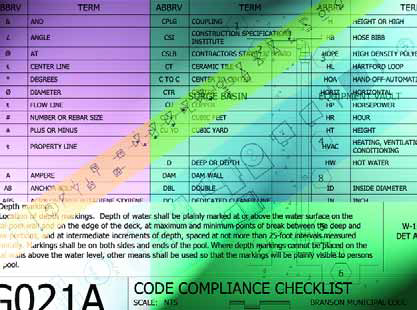
| This is a partial Code Compliance Checklist for a large commercial project. In this case, the plan checker was able to review this complicated project, 26 sheets in all, in very little time and with few corrections. |
Many of the topics are specific to buildings (general information, room-by-room emergency egress patterns, accessibility issues and the like), and most watershape projects do not require these considerations – unless, of course, you build indoor projects, in which case there’s great value to this part of the NCS.
We’ve used this module as a springboard for developing our own Code Compliance Checklist. We essentially established a table in our drawing set that lists the health department’s requirements in one column. In a second, we indicate the relevant sheet and detail number (as applicable) where the specific requirement is handled.
We generate these checklists by copying a specific county’s code from its Web site directly into our table, then refer to it and update the checklist throughout the design process. The list usually occupies a bit more than a full D-sized (24-by-36-inch) sheet – a bit daunting in appearance but incredibly useful just the same.
|
Point of Order To this day, most watershapes are contracted as design-build projects in which the contractor is held responsible for execution and workmanship. This is in distinct contrast to the more widespread design-bid-build process pursued in other sectors of the architectural/engineering/construction (A/E/C) industry, where architects and engineers define performance requirements, physical qualities and standards of workmanship – and projects then go to bid among firms that compete to install equipment, assemblies and systems defined in the design process. This distinction has much to do with why most watershapers, while they may be familiar with the use of notes in drawings, have managed to avoid involvement with detailed, written specifications. That picture is changing as projects become more sophisticated and integrated: Design-build may still dominate, but in years to come it will increasingly be important for watershapers to learn the language of our A/E/C colleagues and adhere to their communications practices and standards. D.P. |
As I have mentioned repeatedly throughout this sequence of articles and columns, the National CAD Standard is not required by law or code, but it still has much to recommend it to watershapers. As I see it, the real value is that you don’t need to reinvent something that teams of people have already established through years of coordination and consensus. Better yet, our increasing familiarity with its provisions raises watershapers’ standing within the A/E/C community and makes it much easier for us to fit into project teams.
In that community spirit, I’m pleased and proud that I’ve been getting plentiful feedback from watershapers who’ve read these discussions of the NCS and are starting to look at their drawings from both technical and development-process viewpoints. There is method to this seeming madness, and it’s encouraging to learn that many of you are coming along for the ride!
Dave Peterson is president of Watershape Consulting of San Diego, Calif. He’s been part of the watershaping industry since 1994, starting his own firm in 2004 after stints with an aquatic-engineering firm and a manufacturer. A registered civil engineer, he now supports other watershape professionals worldwide with design, engineering and construction-management services and may be reached via his web site, www.watershapeconsulting.com.