


Section Dissection


In my last “Currents” column (June 2009), I began a discussion of Project Manuals with an overview of these written specifications and other construction documents and how they are formally bound and made part of a project’s contract documents. This time, we’ll dig inside the manuals and take a closer look at what they contain.
Let me start with a simple recommendation: If you don’t already work with Project Manuals in some form, now is probably a good time to get started – especially if you’re a watershaper who prepares designs to be built by others, but also if your approach is to design as well as build. As I see it, having them is the surest way possible to ensure that projects are built as intended, whether it’s by a separate watershape-construction company or by your subcontractors.
Practically speaking, this documentation clears the path toward ensuring quality installation. At the same time, it’s also a way to impose responsibility for achieving that defined level of quality on every project participant through the entirety of the construction process.
ONE SECTION AT A TIME
To keep things organized, project specifications are generally individualized for each different type or category of equipment or assembly involved. In our manuals, for example, we have separate sections for Valves, Shotcrete and Startup Procedures rather than combining them as a single section, basically because the requirements for one have little or nothing to do with the others.
As assembled, the Valves section might include information on many different types of valves (ball, needle, swing-check, butterfly, vacuum relief and others), simply because the requirements you might list for one valve would be common to valves of other types as well. As an example, one requirement in the valve specification might be that “handles, when present, are to be positioned with the shaft oriented vertically” – unless the pipe run is vertical, in which case “the handle shaft should be oriented facing the front of the equipment.” This is a requirement that applies to all types of valves, so there is no need to divide the valve specification by types and then repeat the information over and over.
Audience is another consideration in the organization of the individual sections. The Valves section, to use it as an example once again, will be reviewed by a plumbing crew that is highly unlikely to read the Shotcrete section despite the fact that the two trades interface at pipe penetrations. For this reason, it is common for specifications to cross-reference one another where coordination is an issue: Thus, the shotcrete information might comment on the potential for shadowing caused by the plumbing’s waterstop flanges: In such a case, a reference to the plumbing specifications will provide more information about the size and potential locations of these flanges to guide the shotcrete crew.
The Construction Specifications Institute (www.csinet.org) is responsible for the organizational structure of the specifications and has divided the A/E/C industry into certain Divisions. It has also assigned Section numbers to keep one consultant’s information from overlapping with others when everything is combined into a Project Manual. Watershapers are part of Division 13 – Special Construction, which includes Sections dividing the industry into specific categories, such as Section 131200 (Fountains) and 131423 (Amusement Park Rides).
Our specifications are mainly included in Section 131100 (Swimming Pools), but when we design commercial fountains, we renumber our documents accordingly. CSI’s MasterFormat standard also allows for two-digit suffixes preceded by dots, thereby dividing disciplines into subcategories. With a pool project, for instance, we might name these subsections as 131100.01 (Shotcrete), 131100.02 (Valves) or 131100.03 (Startup Procedures).
Each of these sections can be prepared and maintained individually, but we prefer to place ours all in one big file that is currently 137 pages long and has some sections of a single page and others that have multiple pages. As we see it, keeping everything together makes individual items within the file much more “portable” as well as easier to edit. For example, if I add a requirement to the information I already have for “perforated drain-pipe used behind retaining walls,” I may want to copy that same requirement to the specifications for pool subdrain systems that use the same perforated pipe.
The best way to keep specifications current, in our view, is to work with master listings before copying files to a specific project folder and then editing down. This way, work done once can easily be recycled for future projects. (And yes, there are database systems for maintaining these documents, but they’re generally used by big architecture or engineering firms that maintain full staffs of specification writers.)
TRIPLE PLAY
Within each Section there are three major parts: Part 1 – General (that is, administrative and procedural requirements for the section); Part 2 – Products (product and fabrication requirements in place before installation on the job site); and Part 3 – Execution (on-site requirements such as installation procedures and schedules).
[ ] The General part of the valve specifications, for example, might require that the contractor submit to the architect or engineer the product cut-sheets for the actual valves that will be used. Our sheet might list a few manufacturers of approved ball valves, so the contractor can’t simply substitute any alternative without written approval. The General part will also include things such as information on abbreviations, definitions, referenced standards (ASTM or ASME), sequencing, certifications, delivery, storage, handling and warranties. CSI’s SectionFormat supplies the outline for these topics. [ ] The Products part will list approved manufacturers, materials, finishes, colors, performance characteristics and other important information about the products or assemblies that will be basically ready to go when delivered. For example, our valve specification covers an Asahi-America Omni Ball Valve with Teflon seats and a CPVC housing that may be required for certain high-heat or ozone applications. The contractor will be held to this high standard as required in order to complete the installation at hand. [ ] The Execution part addresses the product or assembly in light of the installation itself. This might require specific installers or installer certifications, pre-installation testing (for, say, concrete colors), on-site protection, special installation techniques, interfaces with other work, startup, cleaning, close-out procedures and other tasks. The valve specification, for instance, would include requirements for priming and solvent welding using primers and glues identified in Part 2 – Products.And if (for some reason) these primers, glues, Teflon tape, plumber’s putty and other products are handled in another section (such as Plumbing?), then the Execution part might simply make reference to that other section so the information is not duplicated.
CSI’s format is somewhat rigid up to this point, such that if one or two of the Parts are not used they are still listed as being “Not Used.” In the next levels down the hierarchy, however, the structure and content are treated with greater flexibility.
So far, we’ve looked at Divisions with multiple Sections (each having three Parts) as they are used to organize a Project Manual. Now we can further break the Parts down into Articles, Paragraphs and Subparagraphs – all filled with useful details.
[ ] Articles are subjects within a Part that have one or more related paragraphs and subparagraphs. CSI includes a list of these Articles in their SectionFormat document, and if this system is followed (as it should be), it makes each section flow fairly well with a consistency of organization from one section to the next that makes things easier for anyone using the documents. (In the example provided as Figure 1, the Articles are the bold items indicated as 1.01, 1.02 and so on.) [ ] Paragraphs are components within the Articles, and once again CSI provides a good outline to follow. In Figure 1, for example, the References article contains three Paragraphs – one each for Abbreviations and Acronyms; Definitions; and Reference Standards – all suggested by CSI and identified with letters per CSI. [ ] Subparagraphs provide further parsing of the information, and these are generally used by the compiler to cover topics suggested by CSI. In Figure 1 (below), we show this with a subparagraph under Reference Standards in which we require that the contractor must use valves meeting the NSF/ANSI-61 Standard.CSI’s SectionFormat approach is quite thorough, but in common use it is unlikely that all sections will call for using the suggested range of articles, paragraphs and subparagraphs. That said, this layering of information can be quite useful in making certain a given product is used as the designer intends, for example, or in pursuing details related to a concrete mix design or preparation for plastering.
Another tool CSI has provided is their PageFormat standard, in which they describe how each page should be prepared with respect to formatting, fonts, margins, indentations, layout and other details. All that may seem trivial, but the overall purpose is to give everything a standardized look so that when all the sections are assembled into one Project Manual, it will be consistently readable.
TAKING CONTROL
In my first column on this subject, I suggested that anyone not using written specifications should start developing them by listing solutions to problems already encountered. At the very least, doing so should help eliminate repetition of the same difficulties.
Adding that point to the further introduction to Project Manuals provided by this column, I’m hoping that you’re beginning to see how much more control the implementation of such a system will give you over your projects. It’s easy to indicate that a ball valve, say, is required for a certain function noted on a plan, but if you leave that single detail to the contractor or subcontractor without further instruction, it is likely the product installed will be substandard, difficult to maintain or at best the cheapest available option.
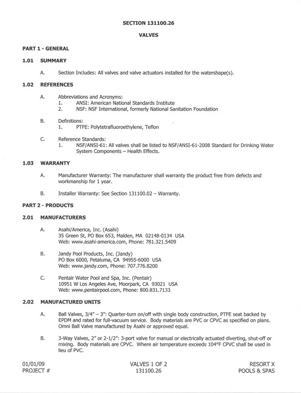
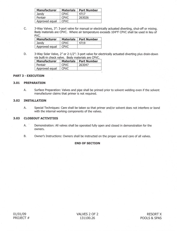
| FIGURE 1: Here’s a typical Valves section from one of our Project Manuals. If this sort of structure is followed, it allows for remarkable clarity in communication about products and their applications — and gives a designer far greater control of how a project will look and perform once complete. |
There are, for instance, several swing-check valves that cannot be maintained and must instead be cut out and completely replaced. In our specifications, we remove the wiggle room, take full control of what can be used and make certain we require use of check valves that can easily be maintained or serviced without ever touching the plumbing.
In that sense, our specification sheets have become an approved product list that we have researched and validated. I’ve made some mistakes in product selection in the past – mainly because I’ve taken leaps of faith and given new approaches or technologies a try. Now we filter out that noise, using our documents as an approved equipment/assembly list.
This isn’t to say we never use new products – far from it. It’s just that now new products must prove themselves before becoming part of our standard list of recommended selections. In fact, what we’ve found is that specification writing done to follow CSI-formatted methods requires research – sometimes lots of it.
That’s what makes these specifications so valuable to us: By the time I’ve finalized a particular specification or edited an existing one, I am reasonably confident in what I am recommending (“should”) compared to what I’m requiring (“shall”) and am assured that we’ll never pick something knowing there’s a better alternative. In other words, we choose the best for our clients, every time!
This in no way should be taken to imply that we use the same products or systems on every job. Each project is different, and one thing we particularly like about the CSI approach is that our file completely documents the performance criteria for competitive products.
In most of our projects, distinctions in competitive equipment are small enough that that their prices seldom vary by more than a hundred dollars or so, meaning we don’t need to make firm recommendations. Some projects, however, will include specialized equipment such as very large engineered pumps or customized, large-diameter sand filters – in which case a competitive bid process could result in substantial savings. In the latter case, we may need to describe (in excruciating detail) all of the material and performance requirements of the equipment so that the contractor is really deciding on cost and not on qualities that we’ve already defined in the specifications.
We run into these competitive-bid situations mostly in publicly funded projects, or in instances in which the client already has certain products installed and wants us to stick with them so operator training is minimized and stocks of spare parts can be exploited. I think that’s a great idea – with the sole caution being that, as the designer or architect/engineer of record, you’re ultimately responsible for the specifications and can’t just sign off on such a request without doing the research and at least recommending changes as necessary.
GRAPHICALLY SPEAKING
Drawings are, of course, the primary vehicle for conveying graphic information, and specification writers are not precluded from using them in Project Manuals. In fact, this can be a great place to stockpile product images or specific drawings that will be valid for every project in which these products or systems are used. That said, I wouldn’t want to use any project-specific graphics in this context; instead, I would use generic images such as details highlighting the code requirements for J-box heights above grade and maximum water levels.
|
Resources: The accompanying text is no more than an introduction to the layers of detail built into Project Manuals and the specifications they contain. To learn more, you can take classes and even pursue professional certification as a specification writer. If you’re looking for basic information, you’ll find good references in the SectionFormat/PageFormat publication available from the Construction Specifications Institute on its Web site, www.csinet.org. It’s available for a fee of $60 to CSI members, $75 for non-members. D.P. |
Another great use of graphics in specs is for architectural items such as outdoor lighting. Here, the designer might set up a product specification for “Path Lighting” that includes, for example, photos of each fixture identified with a label (PL1, PL2 and so on) that matches the nomenclature used on the plans.
This enables the client to look at the plan and reference the specifications to determine exactly what to expect. Also, these details are easily recycled from one job to the next with little or no editing – and it all adds up to make the designer look like a complete professional. It’s easy in this case to add a statement that not all fixture types will be used for the project – a note that will allow the designer to reuse the specification without further edits.
Personally, I also like to use a lot of tables in our specifications. It might just be the engineer in me, but I find tables useful in so many ways that I can’t help forcing certain data into a table whenever possible. Whatever it takes: My ambition is to make these project documents represent my best thoughts on what should happen on site – and use them to make certain those who are doing the installation work have every opportunity to follow my plans to the letter.
Dave Peterson is president of Watershape Consulting of San Diego, Calif. He’s been part of the watershaping industry since 1994, starting his own firm in 2004 after stints with an aquatic-engineering firm and a manufacturer. A registered civil engineer, he now supports other watershape professionals worldwide with design, engineering and construction-management services and may be reached via his web site, www.watershapeconsulting.com.