Water in Transit
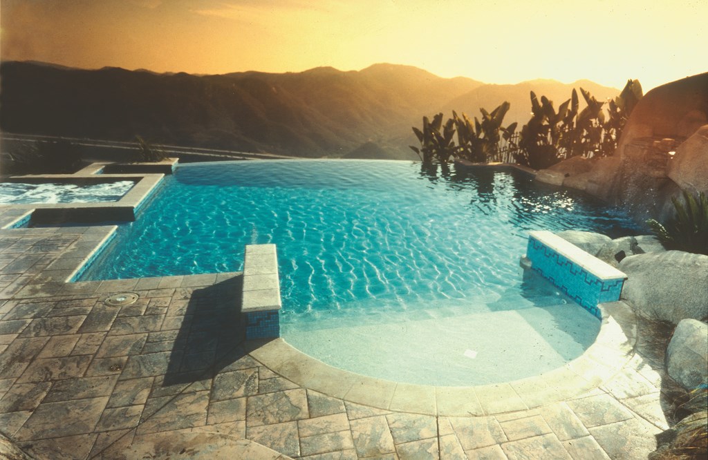
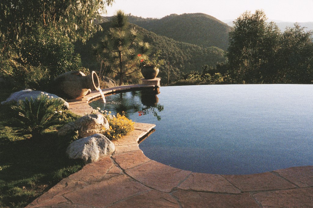
Vanishing-edge pools are all about changing the relationship of the water to its surroundings. They enable the water to reflect views and create visual links to the surrounding scenery in dramatic and surprising ways that simply can’t be achieved with conventional designs.
The same distinction is true of perimeter-overflow systems and pools with deck-level (or slot-overflow) designs, which is why I classify all three together as “water-in-transit” systems. There’s a lot of diversity under that big conceptual umbrella, but these pools share important characteristics and require similar approaches in design, engineering and construction.
The similarity begins with a common definition: These are systems in which water flows over an edge from a primary vessel into another, usually smaller vessel that is designed to accept a constant flow of water needed to maintain the primary visual effect as well as the anticipated surge in flow that occurs when bathers jump into the main pool.
Through the years, I’ve participated in many discussions about these designs in trade show seminars, during Genesis 3 schools and in the pages of trade and consumer magazines. I’ve found along the way that, even though it’s difficult to define a standard in specific mathematic terms (except for a few key parameters), there is a set of key considerations that lead to success.
AT THE EDGE
Any design project begins with evaluation of the setting, the surroundings, lines of sight, elevations and all of the idiosyncratic, site-specific factors that drive aesthetic decisions. As those factors are weighed, only then do practical issues of how things are done and how aesthetic effects can be accomplished come into play.
We’ll come back to the aesthetic issues later, but I want to start with a tangible, practical consideration – specifically the fact that any water-in-transit system involves you in sending water over an edge, which means you also have to capture that water and re-circulate it.
The systems used to accomplish this trick can be broken into two distinct categories: attached or detached surge systems.
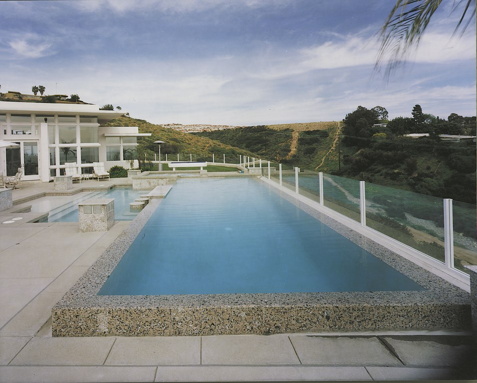
* The attached system is most often represented by the familiar cross-section of a vanishing edge where the trough is two feet wide, two feet deep and two feet below the edge, with those dimensions varying, of course, based on a variety of factors such as the elevation of the surge tank, the length of the edge and the desired surge capacity.
| BREATHTAKING: Aesthetics are important for vanishing-edge projects, but so is precise, up-front control of a range of hydraulic and construction issues that settle into the background once the water begins to flow. |
* By contrast, you can capture the water in a smaller gutter or a perimeter overflow slot and rapidly transfer it to a detached surge tank. These remotely positioned systems give you a great deal of flexibility when it comes to locating and concealing the surge capacity.
There are significant differences between these surge designs, but your basic responsibility remains the same: You need a container that can accept and contain the constant flow of water over the edge as well as any bather surge you anticipate. This means that, irrespective of the vessel you’re using to accept the surge – whether it’s a catch basin or a remote surge tank – you must establish both the minimum operating level of that vessel and its overflow level.
Both of these are volumetric issues determined by how much water will flow over the edge. The minimum operating level (MOL) is the easy part. It’s something you can control with an automatic fill device and calculate accurately once you know the length of the edge and the lift and flow over it. (For the record, I always opt for solenoid-controlled automatic-fill systems rather than float systems.)
By contrast, the overflow level is much less controllable because you can never really know how many people might jump into the pool at the same time. At Questar Pools, we base the volume of the surge tank or trough on two inches of displacement over the entire surface of the pool. It’s a simple calculation: just multiply the surface area of the pool by 7.5 (the number of gallons in a cubic foot of water), then divide that number by 6 (two inches is a sixth of a foot). This gives you the volume in gallons for two inches across the entire surface of the pool.
You could also calculate the estimated displacement of a given number of people in the water. That would be better than no standard at all, but it’s not very accurate given the fact that when people jump or dive in, their level of displacement far exceeds displacement predicted by body mass alone and is impossible to anticipate.
WIGGLE ROOM
In the aerospace industry, designers and engineers are always considering the possibility of catastrophic events. This leads them to build redundancy into their systems and to anticipate the limits of system tolerances.
Designing for surge capacity is similar, and I always suggest erring on the side of over-sizing the vessel you’re using to capture the water. If you have a small pool that you think may occasionally receive extremely heavy use for some reason, then design the system using three inches of displacement as the criterion instead of two, for example. It certainly can’t hurt anything – and in fact might create a buffer that could help you avoid disaster down the line.
Another consideration here is the gravity-fed overflow plumbing. In too many cases, I’ve seen projects in which the surge tank is of adequate size, but the builder considered neither the minimum operating level nor the location of the overflow pipe. If either the operating level is too high or the overflow is located too low (or both), you can reduce your surge capacity through their interaction without knowing it.
When you make this mistake, you find yourself in a vicious drain/overflow cycle: When several people jump in the water all at once, the surge tank will overflow in rapid order and lots of water will be sent to waste via the overflow pipe; when everybody climbs out, the surge tank runs out of water well before the water in the pool can breach the edge again.
| MORE THAN MEETS THE EYE: Perimeter overflows can be spectacular, but they’re nothing without correct calculation of the surge capacity, proper sizing of the piping and pumps, careful attention to the slope of the drainage slots and uncompromising precision in edge construction. |
The same holds true for gutter or slot-overflow systems, both of which can be set up to accept the entire surge on their own or transmit it to a surge tank. If you have a gutter system, you can safely assume that almost all of the water will predictably be caught in the gutter system. With a slot overflow, however, you must assume the lots of water will flow past the slot and will need time to drain back into it – and will do so only if the deck is pitched to direct the flow.
In addition, if the water moves from a gutter system to a separate surge tank, you’ll need either to create the gutter with a pitch that sends water rapidly to some collection point, or you’ll need to establish plumbing connections beneath or alongside the gutter. Both approaches work well if you set things up properly.
With slot overflows, there are a handful of other key issues. In systems that are designed so that water moves into the gutter or slot and flows out one end into a surge tank, for example, you can have issues with debris. To keep the channels clean, you either need to be prepared to flush the system manually or (as I prefer) ensure the fact that the water will move rapidly enough in the system to flush away any debris. This is typically accomplished via a system that includes a plumbing loop and multiple drainage connections to the surge tank.
In these systems, you’ll also need to protect against backflow as well as take steps to avoid the excessive noise that can occur as a result of water flowing into the slot or pouring into the surge tank. The solutions to these potential problems are complex and go well beyond the scope of this article.
(It’s also relevant here to point out that expertise in water-in-transit systems requires far more detailed information than can be found in any single article. The Genesis 3 Schools offer a much more comprehensive look at water in transit that includes, for example, detailed examination of noise-reduction issues as well as many more fine points of construction.)
GENERAL HYDRAULICS
Beyond the basic system-design issues covered so far, much of what it takes to achieve a successful water-in-transit system has to do with hydraulic calculations, including consideration of turnover rate, line size and component selection – basic stuff, certainly, but of critical importance with these systems.
In teaching about water-in-transit pools, I’ve found that many people want to follow “rules of thumb.” If you’re among those who like these handy guidelines, let me warn you away from one that causes problems: the pool industry’s minimum standards for hydraulic design with reference to water in transit: The recommended line velocities of eight feet per second for suction lines and ten feet per second for discharge lines will leave you no room to maneuver!
I prefer to use lower line velocities as targets – a maximum of seven feet per second for both suction and discharge lines. In most cases, what people will find is that as they increase their line size, their flow rates will continue to increase if they use the same size pump, while line velocity decreases. I steer clear of minimum line-velocity standards altogether by always upsizing the plumbing if I get anywhere close to seven feet per second.
| SIMPLE TRUTHS: Water-in-transit systems are challenging for both designers and builders, and it’s partly because there aren’t many generalizations or formulas that make things easier. In my experience, in fact, each system must be approached individually, with no short cuts. |
For primary circulation in most systems, we use half-horsepower pumps on a minimum of two-inch plumbing, 2-1/2-inch plumbing on systems that use 3/4-horsepower pumps and three-inch plumbing on lines with one- to three-horsepower pumps. Almost invariably, these alignments of pump and pipe will keep us well below seven feet per second.
We also use line-size valves and check valves. After all, there’s not much point in using three-inch plumbing if you’re restricting the flow with two-inch valves. For similar reasons, we also make sure that all of our equipment is installed with line-size connections.
The way we look at it, we live in an imperfect world. As much as we might try to account for every single elbow and every single component in completing our hydraulic calculations, we believe in giving ourselves a buffer when it comes to pump and line size.
Going back to my point about the aerospace industry: We want precision, but we also want to maximize the operating ranges in which the system will deliver best results.
THE EDGE FACTOR
Once you’ve established surge capacity and basic hydraulic design, the edge detail itself is the next critical element you need to address. The key considerations here are the edge length, tolerances and the edge detail itself.
[ ] Edge length: This is both an aesthetic and practical issue. With a vanishing-edge pool, you can get to a point where you’re designing an edge that’s so short, you may need to question whether or not it’s worth it. My personal rule is to consider 20 feet as a minimum length for our edges.
This is entirely subjective, but I’ve found that for the design to make sense visually and in terms of the budget, 20 feet just seems to work. In more practical terms, a trough that’s only ten feet long, say, might be difficult to design with adequate surge capacity.
|
Responsibility The unfortunate reality of many vessels with water-in-transit designs is that the people designing and building them have only a vague grasp of basic hydraulics and precision construction, both of which are essential with these projects. If you’re overmatched when it comes to sizing a line, a pump, a skimmer and a filter, there’s no way you’re ready to jump into water-in-transit designs. Similarly, if “close” is good enough for you when it comes to construction tolerances, these are projects that will come back to haunt you, financially and probably legally. That said, it’s important to bear in mind that hydraulic-design parameters, tight tolerances and all of the other things you need to do and keep straight are attainable if you take care, have pride in your work and, above all, understand the primary responsibilities that are part of the deal when you tackle one of these projects. That’s true for any watershape, of course, but you can assume that those responsibilities are dialed in at a much higher level with water-in-transit designs. The stakes are higher if only because you often face situations in which a mechanical or hydraulic failure can go from being a mere nuisance to become something catastrophic. So instead of mundane complaints about a pump that fails prematurely or a system that is too noisy or one for which operating costs are too high, you can face flooded yards or structures and the real possibility that you might lose the entire vessel to an undermined slope. — S.P. |
That’s a generalization, of course, and there can certainly be exceptions, but let’s take a look at a typical 800 square-foot pool to illustrate. Say you want to lift a quarter inch of water to flow over the edge of that pool: This computes to about 125 gallons at a time flowing over the edge. If the edge is 30 feet across, that flow can easily be captured in a traditional trough that stretches across the full 30 feet below the edge.
If the edge and trough are just ten feet long, however, the standard trough will be too small, which means you’ll need to make the trough larger in dimensions other than length. With close edge tolerance, which I’ll discuss below, calculating edge flow is really very easy. Again, the tough part comes in allowing for the surge capacity.
That re-dimensioning may not be visually desirable or practical from a structural standpoint. By the same token, if you’re working with a design where the edge flows over into a large body of water – an open, shallow kiddie pool, for example – the concern over edge length may be irrelevant.
By the way, this set of considerations is another good reason to calculate displacement by surface area, because it forces you to acknowledge that you’ll need to capture a given volume of water no matter the length of the edge or the edge detail. The flow rate may change, but the basic functionality of the system will be the same.
[ ] Tolerance: This is perhaps the most critical of all the elements of a water-in-transit system, because without knowing your edge tolerances, you can’t effectively calculate or even control the flow rate over the edge. As a rule, the lower your anticipated flow rate, the greater the need for tight tolerance across that edge. We prefer working with low flow rates, so we nail our edges, plus or minus, to within a sixteenth of an inch.
| LINES OF SIGHT: There’s nothing that says vanishing-edge effects work only with nosebleed or waterfront views. If the reflections work and there’s an opportunity to tie the water into landscaped views, I’m all in favor of putting pools on flat or nearly flat lots. |
How difficult that is to achieve depends on the material. For my own backyard pool, for example, we built a 55-foot edge that’s set in random stone – and we’re flooding it with a one-horsepower pump on three-inch plumbing. The flow over this edge works out to something less than three gallons per minute per foot. For many builders, that might seem like an impossibly low flow rate, but because we used a grinder to fine-tune the edge after it was installed, we’ve been able to accommodate that low flow rate consistently across the full length of the edge.
The flow rate you want over the edge will also vary widely depending on the effect you want to achieve. For systems that are viewed from the house side – that is, with the water falling away from the observer – you typically can’t tell if the edge is flowing at 100 gallons per minute or two gallons per minute. The thought to bear in mind is that there’s no real “standard” for flow rate – but there is a responsibility to ensure that whatever rate you target is being achieved on the full length of the edge.
Trouble can start quickly when you try to overcome a loose edge tolerance by simply pushing more water over the edge. Often, this involves moving water at or above recommended line velocities after the fact to achieve the necessary flow, which can lead to increased energy consumption as well as to turbulence – the enemy of all water-in-transit systems.
Rule of thumb: Keep your tolerances tight enough so that the vanishing-edge effect works with a minimal flow rate – say, five gallons per foot per minute maximum – then work up from there if you want to achieve a waterfall effect by pumping up the volume.
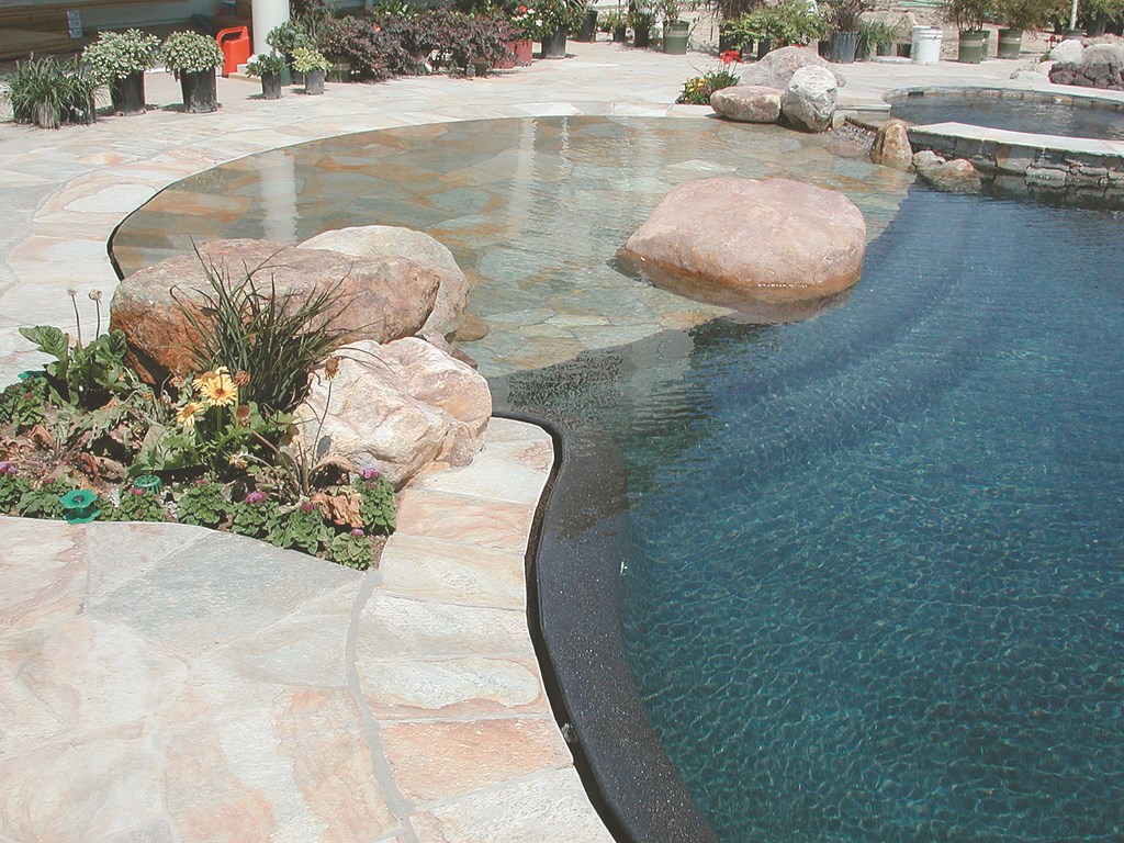
[ ] Edge detail: Virtually from the first of the vanishing-edge designs (and perimeter-overflow designs as well), there’s been a debate over which way the edge should be angled.
We typically pitch the edge away from the pool unless observers are easily going to see the top of the edge wall. In that case, where the physical proximity of the focal points creates a situation in which observers will be looking down at the top of the wall, we acknowledge that you’ll see the top of the edge and pitch it back toward the pool. You still see the top of the wall, but its visual impact is minimized.
This isn’t quite a judgment call, but it’s one that has more to do with aesthetics and appearances than with practicality, which leads us back to a set of considerations that really come first in any project.
BACK TO VISUALS
As I mentioned at the outset, whether you’re thinking about a vanishing edge, a wet edge or a deck-level/slot overflow system, you need to start by thinking about aesthetics and very basic system functions.
I begin, for example, by looking at lines of sight to establish an elevation and location for the pool in relation to the home and the basic topography of the property. Only if it makes visual sense, budget sense and sense for the way my clients want to use their watershape do my thoughts turn to the practicalities of a water-in-transit system.
As it all comes together (and if it all comes together), I’m aware that lines of sight are something I can control – not through the structure of the home, the orientation of the property or by a trick of eyesight, but rather by understanding the ways I can work with the pool’s physical location, shape, size and elevation relative to those other factors.
|
Edge Essentials When it comes to creating a hydraulic system to run an edge effect, I always recommend setting up one that’s independent from the pool’s main circulation system. In many cases, the flow of the primary system will be the same as that of the edge system. In those situations, there’s a nasty cost-cutting tendency to think you’ll be better off combining the systems and using only one pump. The problem with that notion is that you now have to control whether you’re drawing water from the surge tank or from the skimmers – which means that the suction side plumbing must be interconnected in some way. As a rule in these water-in-transit systems, you should always use an atmospheric vacuum breaker to protect water on the discharge side, meaning that if the check valve fails, the vacuum will be broken and won’t allow the pool water to back up into the surge tank. In a shared system scenario, unfortunately, you can’t protect the suction line in that way: When you cross-connect your suction lines and the check valve fails, the pool will drain independent of the protection system used on the discharge side. Everyone in this business should know that check valves do fail, and it’s less a matter of if than it is of when. This is why we recommend creating edge circulation systems that are independent of the primary circulation system of the pool. There are certain other mistakes that you need to avoid. * Number one is locating the pump above the source. Assuming that the operating surge tank level is five feet below the pool, just imagine trying to block off all of those suction grates and trying to flood the line uphill to the vanishing edge pump. It’s a prescription for failure, which is why the pump should always be at or below the source – end of discussion! * Number two is returning unfiltered water through the vanishing edge discharge. All this does is take the debris that collects in the surge tank and then return that garbage to the pool, unfiltered, via the vanishing-edge return lines – thereby further shortening the life of any check valves in that part of the system. * Number three is relying on a check valve to separate the surge tank or trough from the pool. We all know that check valves fail, and I can guarantee you that your surge tank will not accept the full 20,000 gallons of the average pool’s water (unless you’ve gone way overboard in upsizing your system against the possibility of catastrophe). If you have check-valve failure, the water will pass by the overflow in the surge tank like it’s not even there. It will flood the surge tank and, in the case of a vanishing edge, will completely flood whatever slope or level ground is adjacent to the catch basin. The erosion that occurs, left unaddressed, is a good way to lose the entire structure – all because you chose to rely on a device that is certain to fail at some point in time. I see atmospheric vacuum breaks as cheap insurance. If you don’t know what one is – or, worse, choose not to use one because of their tiny cost – then I’d suggest you have absolutely no business trying to build a water-in-transit pool! — S.P. |
As I examine a setting and consider its potential, I’m aware of the fact that there’s no real point in building a water-in-transit pool of any kind if it won’t work visually. I’m also keenly aware of the fact that water-in-transit designs are primarily about reflections – my touchstone when I consider placement and orientation of these watershapes relative to their surroundings.
We’re all certainly familiar with vanishing edges that fall over nosebleed drops, often with echoing bodies of water in the distance. These projects may seem as simple as rolling off a log, but they work best when the designer sets the outer edge in relationship to primary focal points that govern where the visual boundary exists. In other words, if you do things right, you modify the lines of sight with the presence of the pool structure itself – and the effect of water flowing over the edge serves to link the reflections on the surface of the water with the near or distant views to which the eyes are being led.
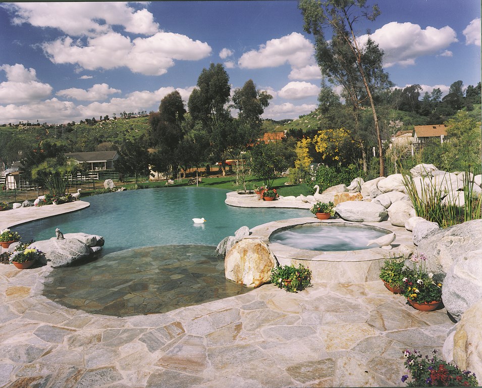
Hilltop edges with perfect, open vistas are great, but personally I enjoy designing vanishing-edge pools in conjunction with landscaping. I’m also working more and more with water-in-transit systems on flat or near-flat lots. Plants, particularly large ones such as trees, offer wonderful opportunities to modify lines of sight, both by concealing views that are undesirable and by leading the eye to views you want to see by defining visual “corridors.” In many ways, I prefer working in these settings because of the opportunities they offer to connect the structure, the reflections and the surface of the water more intimately with the surrounding environment.
As I ponder the possibilities, I bear in mind that perimeter-overflow designs offer effects similar to those of vanishing-edge pools through the dramatic appearance of water flowing seamlessly across the entire confines of the pool or even a section of it. I’m also aware that deck-level or slot-overflow systems don’t work the same way: Where the other water-in-transit options lead the eye beyond the water’s edge, slot overflows keep the eyes fixed on the edge itself.
All these factors must be weighed, discussed in detail with the clients and visualized in very clear ways before you get serious about how you’re going to pull off the effect and make the system work.
NOT ROCKET SCIENCE
To be sure, water-in-transit systems are more complex than many other types of watershapes, but they are not so difficult to execute if you keep the considerations I’ve discussed above firmly in mind as you proceed.
Because I’ve developed a reputation for knowing how to build these systems to a high standard, I’ve been asked many times to offer my opinion on projects where things have gone wrong. The trouble almost always comes down to a basic lack of understanding on the part of the contractor of proper hydraulic design, sufficient surge capacity or good edge tolerance.
I would suggest that if anything I’ve described above seems foreign to you, you’re much better off steering clear of these designs until you learn more. If you do step up to the plate and take on a water-in-transit system, then begin that process with a clear understanding of your responsibility to your clients followed by careful execution of the fundamentals of good construction.
Skip Phillips is president of Questar Pools, a high-end swimming pool design-and-build firm based in Escondido, Calif. He started his business in 1975 as a service/supply/repair operation ,moving quickly into renovations and new construction. Now a veteran designer and builder of high-end, custom swimming pools, Phillips has won more than 100 local, national and international design awards. His reputation is tied closely to hillside pools featuring vanishing-edge designs; he is one of only two U.S. instructors currently teaching classes on vanishing-edge pools and has written and participated in numerous magazine articles on the subject. Phillips is a past president of the National Spa & Pool Institute and co-founded the Genesis 3 Design Group.


