


Keys to Consistency


Professionals often seek ways to distinguish themselves in their chosen fields of endeavor. For watershapers and others who work in design- and construction-related disciplines, one prized distinction is consistency when it comes to drawings: It’s something that makes them easier to work with and more valued as collaborators.
Indeed, established firms repeatedly use the same drafting conventions, project after project, to a point where their plans become known and well-regarded for being easy to understand – and their projects much easier to bid and build.
In my last “Currents” column (click here), I began to define the nature and value of consistency in project documentation by discussing the importance of drawing-set and sheet organization. This time, we’ll dig deeper and focus on some of the actual content of the plans – specifically as relates to Module 3 of the National CAD Standards (NCS) on Schedules and Module 4 on Drafting Conventions.
USING SCHEDULES
Let’s start with a quick definition: In the context of drawings, the term schedules refers to tables of information that summarize equipment and various other specifications. Typical sets of documents may also include, for example, schedules for construction or critical path milestones, but this time we’ll focus almost entirely on equipment schedules.
No matter the type, schedules are a fast, easy way to summarize what’s needed for a project. The equipment schedule, for example, helps ensure that the right components and devices are purchased and installed, thus reducing errors and change-orders during construction. And when these equipment schedules include relevant electrical information (as ours do), they are easily understood by electrical engineers who can size up the circuits and ensure that the right voltages will be available at all the right places.
Here’s why this is so important: Have you ever read a plan developed by someone who listed a pump as “2 hp” only? I certainly have, but I know that without additional information it is virtually impossible to select the right pump.
There are, for example, two-horsepower pumps with curves that handle high flow and low pressure – and two-horsepower pumps that produce low flow at high pressure. Even similar pumps made by different manufacturers will have varying performance, rendering “2 hp” completely meaningless.
If the plan read “2-hp Pentair WhisperFlo,” that would be better but would still be inadequate, because that manufacturer offers that pump in energy-efficient models, full-rated or up-rated models, three-phase or single-phase formats and even single-speed and two-speed versions. The best way to make certain the designer’s actual selection gets installed in the field is to provide that information in a pump schedule.
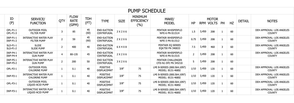
| This is the sort of Pump Schedule that often accompanies our schematics. This way, a given piece of equipment can be called out on the diagram with an identifying code rather than with a full description – a real benefit when it comes to reducing clutter on the schematics. |
To place this in context, let’s back up a bit: Before my company generates our equipment schedules, we always develop a single-line schematic diagram of all hydraulic systems. (This is done immediately after the plan view has been developed.) This schematic helps in validating the plans (with respect to size of surge basins and the like), and we prepare it before we start any structural engineering work because sometimes the schematic diagrams identify operational problems that might affect subsequent plans and structures.
The schematic shows each piece of equipment from the smallest needle valve to the largest filter – but it doesn’t get specific about the equipment: That’s left to the equipment schedule. A pump, for example, might be shown and labeled on the schematic as P1, but the manufacturer and model number of that pump P1 will be listed in the Pump Schedule along with its electrical and performance criteria.
BETTER AND CLEARER
Why not simply list the pump on the schematic diagram?
First, the schematic diagram is already quite detailed, carrying a great deal of information on line sizes, flow rates, velocities and more. There’s so much going on here that the drawing would be quite difficult to read if specific equipment details were listed.
Second, although the schematic identifies some performance criteria (particularly flow rates), there may be many pieces of equipment that may be suited to the purpose and the place to indicate those options is on the equipment schedule rather than the schematic itself. This is especially true with large projects or government jobs that require competitive bids.
Third, nothing will summarize all the equipment as neatly as a schedule. That clarity is especially important for sorting out details such as electrical loads, for example – a huge help to the electrical engineer who needs to develop a plan to handle them.
Fourth, it is much easier to change equipment in the schedules than it is anywhere else. As an example, we recently specified variable-flow pumps for a commercial waterfeature before we had received relevant electrical information from one of the project’s other consultants. Later, we learned that we could only count on getting 208 VAC delivered to the pump (which requires 230 VAC), so we changed the schedule and specified a fixed-speed pump with a motor that could function adequately with 208 VAC.
We also use different schedules for different types of equipment because their requirements vary. For example, a pump schedule might need fields for flow rates and total dynamic head, while heaters need columns for ambient temperature, maximum desired temperature, delta-T and Btus per hour. Formatting a single table to include all the required fields for everything from lighting to chemical controllers would be incredibly complex and highly inefficient, so we break everything out in sensible groupings.
The first column of all the schedules carries the Equipment ID Tag. This tag is referenced in the schematic diagrams, plans, sections and written specifications and distinguishes this piece of equipment from any other that might be specified. For our drawings, we use letters to identify different types of equipment: P for pumps, F for filters, H for heaters and so on.
We also use a three-letter prefix that identifies where the item (a lighting fixture, for example) is located or, with a pump, for instance, where the water originates. This works well in that equipment related to, say, a spa only is labeled as such – even though pumps sometimes pull from multiple bodies of water. (In such cases, you just need to pick one for your labeling because it’s generally more important for the designation to be unique than to be spot-on specific.)
SIMPLE TRACKING
The key in all of this is consistency, of course, but it also requires whoever is doing the coding to have a complete overview of project features and a good sense of what is involved in collaborating across disciplines. In addition, the person doing the coding needs to be both thorough and meticulous. Where there are multiple pieces of equipment, for example, he or she needs to keep track of everything and include suffix numbers to make certain all bases are covered and identifications continue to be unique.
In our business, we mark these identifying codes on the equipment itself during installation. This helps keep things straight with repairs and maintenance in the future (particularly valuable for large commercial jobs).
Ultimately, what we accomplish with all this is making the equipment schedules the single reference point for specifications. In other words, all diagrams, plans, specifications, notes and other references simply link back to the schedule using the Equipment ID Tag – which can be as simple as “P1” or “SPA-P2-1.”
For large jobs, these schedules can multiply like rabbits. In most cases, for instance, we’ll have them not only for pumps, but also for filters, heaters/chillers, solar heating, lighting, autofill devices, chemical-treatment systems, controllers and, as a grab bag for other components such as nozzles, safety equipment, pressure gauges, flow meters and sight glasses, a table labeled “Miscellaneous.”
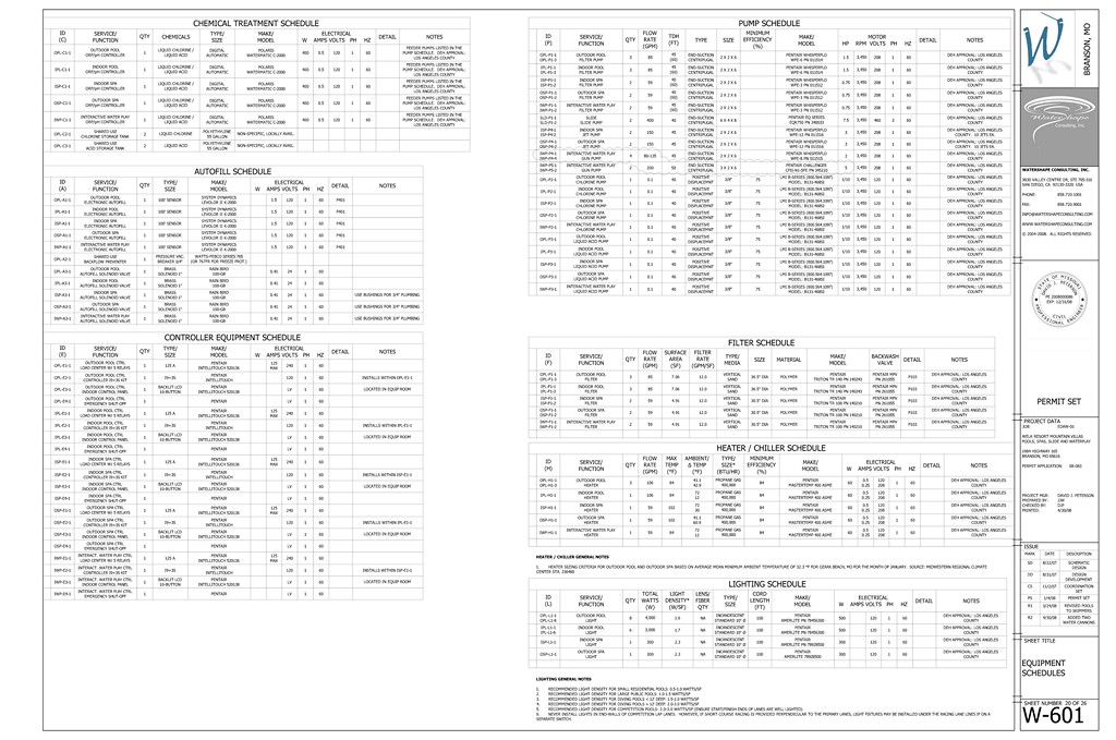
| Once all of the documents are compiled and all the equipment has been added to the appropriate schedules, the collective sheet becomes a shopping list of sorts – a big help in helping contractors accurately assess the scope of work and prepare their bids. |
Our schedules usually require an entire Arch-D size sheet (that is, 24 by 36 inches). We start with a master copy that includes all the schedules filled out with products that we tend to specify over and over. From that starting place, we simply add, delete and edit to make the sheet specific to the job.
Once the editing is done, the schedule becomes the shopping list – the first step in determining an accurate scope of work and preparing a bid.
Helpfully, the NCS includes sample schedules for many project functions, including steel reinforcement, pumps, doors, finishes and much more. It’s possible to establish and adjust the schedules in a spreadsheet program such as Microsoft Excel – but you need to be sure the information can be pasted into the drawing set before committing much time to compiling your basic product lists.
It’s also possible to modify the format and diverge slightly from the NCS model – as we’ve done for our own purposes. In everything we do, however, we follow the spirit carried in Module 3 of the NCS as it relates to the way we set up all of our schedules and use those principles with all of our construction documents.
CONVENTIONAL WISDOM
Now let’s move on to the fourth module – Drafting Standards – which is all about bringing consistency to graphical and textual information conveyed within drawings.
Large firms follow these rules out of necessity because the members of their own design teams may change as projects move along, meaning each employee may need to be able to jump into the process at any time and have his or her work merge seamlessly with everyone else’s.
Some of these conventions deal with simple issues (such as line weights and scales), but they also cover the complexities of mock-up plans of the sort developed at the beginnings of new projects. No matter: The all-important goal here may be summarized as the generation of clear, concise, comprehensive and consistent communication and cross-referencing. That’s a whole bunch of Cs, but what it all boils down to is that we can’t get all of the required information to build a project on a single sheet of paper. As a result, we need to use consistent references throughout any given set of drawings.
One of the first conventions has to do with drawing orientation and north arrows.
Generally, our site plan of an entire property will show the project with true north pointing straight up on the sheet. Sometimes this will be rotated slightly if it means we can show the whole site at a larger scale by taking advantage of a plan page’s aspect ratio, but generally the practice is to have the directional arrow pointing straight up.
Beyond that one sheet, however, most sets of construction drawings are almost always set up with the north arrow pointing in some direction other than straight up.
On most residential projects, for example, we position the entry door at the bottom of the sheet with the backyard at the top so the client reads the plan as if he or she were coming home. This isn’t the site plan: This is a larger-scale construction plan, and if the project is strictly a backyard design, it might even include only the rear walls of the home at the bottom of the sheet, no matter their directional orientation.
The important point here is consistency, not direction: Wherever you set the baseline and no matter the direction of the arrow, all drawings in the plan set must use this exact same orientation, with the overall site plan being the only possible exception.
WORKING THE GRID
Another convention of Module 4 is a grid system that can be used to align and reference certain edges, column lines or other elements in a plan. Using this grid is especially important in multistory buildings to coordinate the activities of trades between floors, but we’ve found it to be useful for layout work in both geometric and freeform watershapes.
Generally, the vertical grid elements are labeled with numbers and the horizontal rows are labeled with letters. The grid does not need to be equally spaced, and sometimes intermediate lines are identified with markings such as “C.4” to represent 40 percent of the distance from row C to row D. If the primary grid is ten feet on center, then C.4 would be four feet from row C. The great thing about a grid system is that it can reduce much of the dimensioning that would otherwise complicate the plan.
The NCS also carries suggestions on how to lay out drawings to maximize plans’ readability and accuracy. Noting dimensions beyond the edges of the primary construction plan, for example, is recommended as a way to reduce clutter within the plan itself. That seems simple enough, but there are several NCS pages on dimensioning that highlight the fact that this information can be critical.
Helpfully once again, the NCS makes suggestions about what exactly needs to be dimensioned. Do you, for instance, dimension the edge of the coping, or is it the concrete structure beneath it? Generally, says the NCS, it’s better to dimension the structural elements and let the finishes float out beyond that – unless, of course, the location of the finish material is critical and the plans need to reflect that fact. This module also gets into vertical dimensioning and suggests working with finish elevations because it is simply unacceptable to have odd-sized steps, unworkable slopes to drains or flawed water levels.
There are also rules regarding scale. No more needs to be written here than that the minimum scale to be used for designing watershapes is one-quarter inch per foot. (The only exception might be a lake-type project where the size is huge and the point-by-point accuracy of a plan is not so crucial.) Naturally, details can be drawn at larger scales, and the NCS does a decent job of explaining that items such as material indications should not be completely shown in certain views lest they complicate the image.
Line weights, line types, arrows, section and elevation callouts, detail references and some symbols are also covered by the drafting-conventions module, and there’s an emphasis on the importance of cross-referencing, which flows from the floor or construction plan (the master drawing) and establishes links to more specific information (details, sections, notes and so forth) on subsequent sheets.
Bottom line: Plans with great cross-referencing never duplicate information and the specific details are always within easy reach.
VALUE ADDED
The Drafting Conventions module is all about organization and consistency of the drawing information, so it is no wonder that it includes a recommended method for organizing the drawing set.
This starts all the way at a project’s beginning with the mock-up or cartoon set – something we prepare for all our large projects at the proposal stage so that we can get our hands around the scope of the work. Our mock-up sets use ordinary 8-1/2-by-11-inch sheets to represent a scaled-down version of the final set of plans we expect to create. We rough out each sheet, verifying that our proposed scales will actually fit when we move to the final documents.
Some of the sheets are marked up with rudimentary sketches, but others are simply lists of what eventually will be included. Our resort projects show why this preparatory work is so important: Large pools need to be split into multiple sheets with matchlines – an effort that will require a little more work in the design phases not to mention higher printing fees throughout the project.
We need to determine all of this during our proposal phase, so the mock-up sets are sometimes done before we even get the project. The real value, however, comes when we get the job and use the mock-ups as a roadmap for all the rest of our design work and as a yardstick that lets us know what percentage of the work we’ve actually completed as the project moves forward.
As an example, one of our recent resort projects included 36 sheets of watershape-specific plans in addition to the landscape, civil engineering, architectural and other plans produced by our fellow team members. It was much more efficient to draw each sheet knowing that certain information was required – and that other information was going to appear on separate sheets.
We were also able to add complete references (such as section lines or details) starting on Day One instead of having to wait to apply those references (which include key bits of basic information such as sheet numbers) until after the first full set of plans was completed. The mock-up set also established drawing priorities and allowed us to split up the work among multiple drafters without losing any continuity within the whole set.
To those of you who are thinking, “We’ll never need a mock-up set for our residential projects,” I say this: While that will be true for most projects, some custom watershapes are complicated enough that we’ve found ourselves developing up to 17 or 18 sheets for a mock-up set. If you are ever invited to design a really big project, in other words, I’d suggest jumping on the NCS bandwagon and using the mock-up process to get yourself organized early.
That’s what the NCS is all about: simplifying your processes by making them organized and consistent from project to project.
Next: Terms, abbreviations, symbols, notations and code conventions.
Dave Peterson is president of Watershape Consulting of San Diego, Calif. He’s been part of the watershaping industry since 1994, starting his own firm in 2004 after stints with an aquatic-engineering firm and a manufacturer. A registered civil engineer, he now supports other watershape professionals worldwide with design, engineering and construction-management services and may be reached via his web site, www.watershapeconsulting.com.