


Custom Contours

This waterfall could’ve been built in either of two ways: A system of internal reservoirs and a long, narrow nozzle could’ve been formed as part of the structure itself, a task that would’ve placed huge burdens on the forming crew and the person shooting the gunite; or a manufactured fixture could be used to create the desired effect.
Sensibly, the folks at Tango Pools in Las Vegas chose to pursue the latter option, deciding it would be better to set up the effect before the structure was shot rather than try to engineer the effect and then sculpt the design with gunite. Unfortunately, however, they discovered that no supplier offered an off-the-shelf fixture with the sorts of curves they were after.
We at Florida Falls were among the companies contacted. The builder sent us sketches illustrating a continuous water wall as well as a set of plans for their engineered-on-site option. The design called for a 39-foot span with concave and convex curves and a slow-moving, somewhat coarse wall of water falling more or less straight down from a protruding ledge.
As was the case with other suppliers, our stock items are all linear. But we were intrigued enough by the look of this project that we jumped right in (despite the fact we weren’t quite certain how to pull off the effect) and started improvising with fixtures we had on hand.
STAGING THE FLOW
To get things going, we treated the system as though it were to be an ordinary, linear waterfall – one we knew we’d have to play with on site to make it work the way the designer wanted it to.
To get as close to the contour as possible without trying to bend or modify larger units, we shipped out a dozen 3-foot “base units” we ultimately linked at the nozzle to form a unified flow. These units have their own reservoirs, complete with internal baffles that can handle a large amount of water and disperse it evenly across a straight nozzle. The nozzle can be narrowed or widened to create different sheeting effects. Each unit is fed by a 2-inch riser connected to a 4-inch plumbing line at the base of the structure.
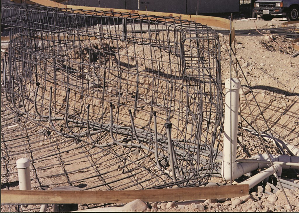
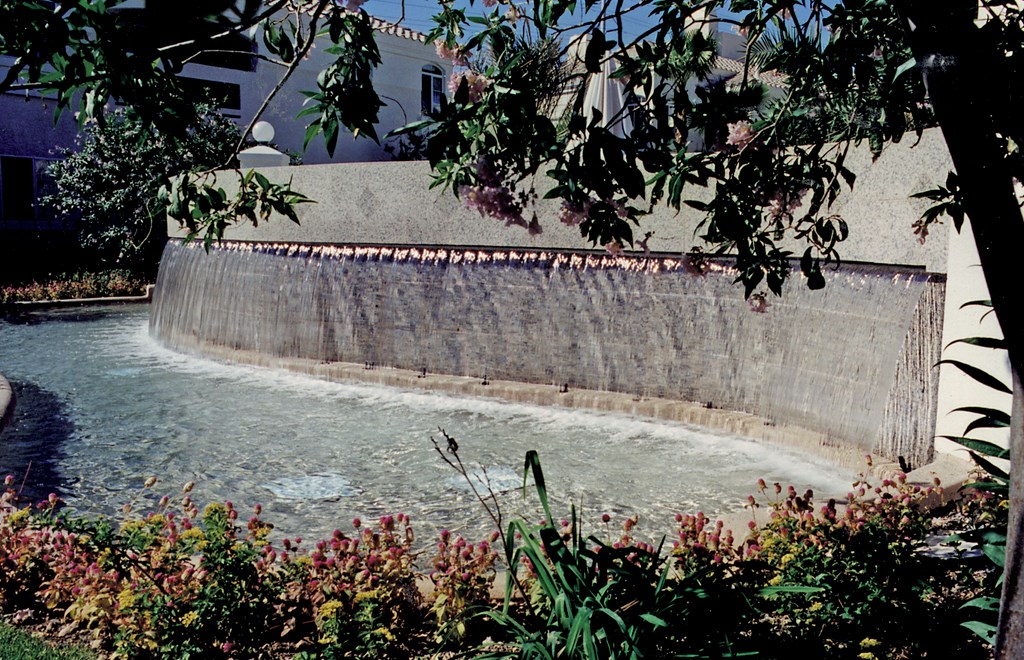
| Figure 1: This graceful waterfall is to welcome residents to an upscale Las Vegas condominium complex. The curves were created using standard linear waterfall fixtures manufactured and then modified on site by a crew from Florida Falls of Spring Hill, Fla. Here, the waterfall’s structural steel, plumbing and electrical conduits are being prepared for insertion of the waterfall’s twelve 3-foot base units. In the process, we leveled the cage to a tolerance of 1/16th of an inch across the 39-foot span of the fixture. |
The pump room for the waterfall was 70 feet away, so we set up the circulation system with a pair of 5-hp pumps feeding separate 4-inch lines. Each line feeds six base units. Two large, grated main drains were to provide the return flow.
Accurate flow calculations are critical for this kind of job and for achieving this sort of effect. We specified the 4-inch pipe to hit a flow rate of about 10 feet per second, which is good for 390 gallons per minute on each line. This all fit nicely with our fixtures: Each base unit puts out about 24 gpm per linear foot at the nozzle. The net result is that this 39-foot feature drops just under 800 gpm into the trough – just what we needed with a 5/8-inch nozzle aperture to create a thick wall of water that would fall nearly straight down.
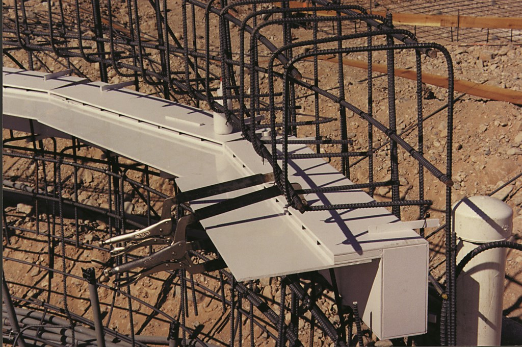
| Figure 2: Once the cage was ready, we inserted the base units and secured them to the cage using small flanges we fabricated and attached on site. We worked with three-foot sections to come as close as we could to the curving contours with the linear units. The first step after insertion involved attaching ABS sheeting to the bottom side of the nozzle. |
Because the plans called for the fall to emerge from beneath an outcropping of gunite, we installed the base units in the structural steel along with the rest of the plumbing, electrical and lighting conduits. This meant we had to hang the base units, connect the plumbing and secure them so they’d stay in position until the structure was shot.
We started by leveling the steel cage using a laser leveling system. Although this wasn’t a case where we really needed dead-on tolerances, we leveled the structure to within 1/16th of an inch across the entire 39-foot span (Figure 1, above). Then we inserted the base units and glued small plastic flanges onto the base units, extending both vertically and horizontally, so we could tie off to the steel in both directions.
FITTING IN
With the units in place and level, it was time to begin the contouring.
We began by attaching ABS sheets to the bottom of the base units’ existing nozzles (Figure 2, above). Once these pieces had been fitted, we measured out two inches from the front of the steel, checking our progress every couple of inches along the face of the structure so the nozzle would follow the curve created by the cage.
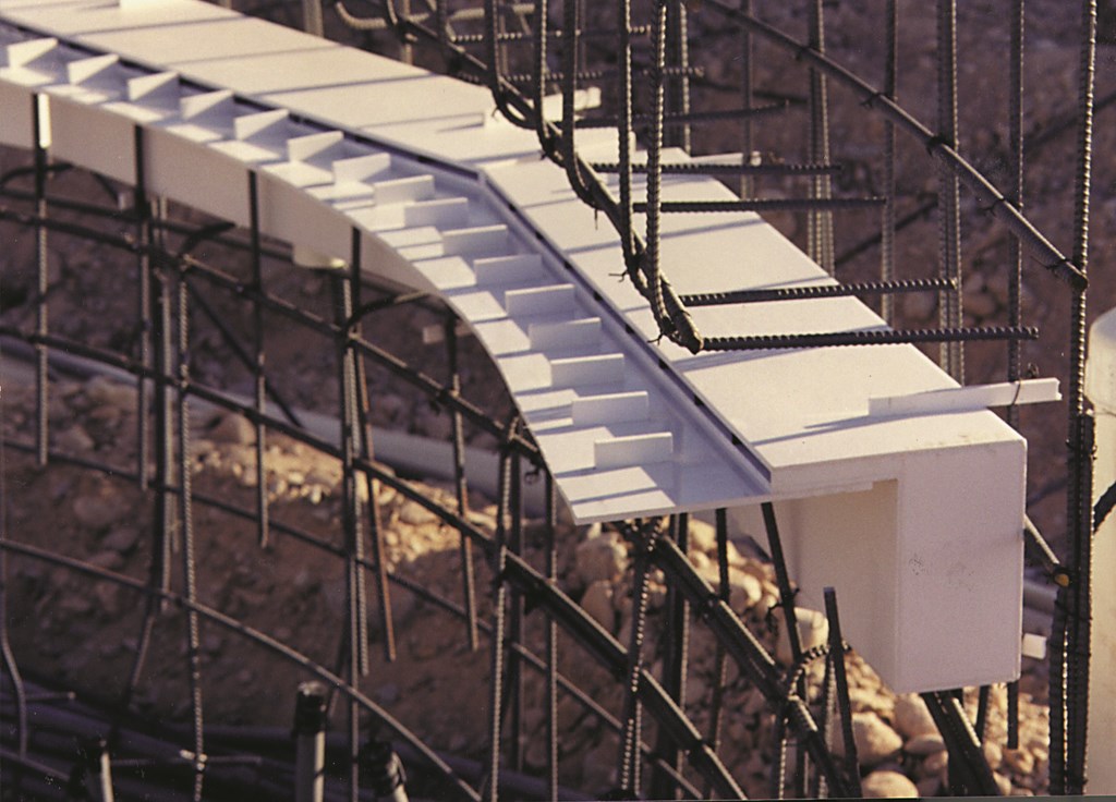
| Figure 3: After we trimmed the sheeting to follow the contour defined by the cage, we set spacers to hold the nozzle at a 5/8-inch aperture and to break the flow of water out of the nozzle at the desired intervals. |
Next, we installed spacers every three inches to support the upper sheet of plastic and maintain an even 5/8-inch opening at the nozzle (Figure 3). Now we glued on the top sheet of plastic (Figure 4).
In order to make this water come straight down, we made the upper lip of the nozzle slightly longer than the lower lip to create a small space in front of the nozzle. Because of the flow rate and nozzle width, there’s very little forward motion – no more than about an inch beyond the nozzle. (That’s not very far and certainly not all the distance of which these nozzles are capable: We’ve done projects in which the water projects seven or eight feet from these base units!)

| Figure 4: The last step in modification involved attaching ABS sheeting to the top of the nozzle and trimming it to the proper contour – thus completing a transformation from the linear originals to this curved wave form. Note that the fixture now will serve as a support and form for the upper portion of the gunite structure. |
We were now ready for the gunite crew, which shot the structure in two stages. In the first phase, they worked up to the underside of the base units and let that set. This structure gave the base units the support they needed to hold up the weight of the big beam that was shot next (Figure 5). We protected the nozzle with tape and made certain the subs took care not to disturb our handiwork.
Soon we were able to fire up the system and watch as the waterfall emerged as a perfect, rough-edged sheet from the hidden nozzle.

| Figure 5: The shell has been shot and the fixtures are now encased in the gunite, ready to produce a glorious visual effect. The structure being framed in the background houses the waterfall’s pumps as well as all of the equipment for the swimming pool sheltered by the waterfall. |
The remarkable thing about this project was how simple it turned out to be to achieve a nonstandard effect using perfectly standard components. Yes, it took some ingenuity and concentration, but once we actually started working instead of thinking about the difficulties involved, the project went forward smoothly – and, as it turns out, very successfully.
All that remained was the finish work: Marble veneers on the vertical faces, gray pebbles in the trough, fiberoptic spots at one-foot intervals across the bottom ledge and the project was complete – and we had a whole new approach to waterfalls we’ve translated many times since to other custom contours.
Ben Dixon is co-founder of Florida Falls of Spring Hill, Fla. – since August 1998 a division of Polaris Pool Systems. A former university instructor, he left the classroom behind in 1981 when he founded The Spa Shop in Gainesville, Fla., to design, install and service inground and portable spas for customers throughout the Southeastern United States. In 1991, his hot-water experience behind him, Dixon and Doug Rutherford founded Florida Falls to manufacture components for residential and commercial waterfeatures. He now routinely consults with pool designers and builders on high-end projects throughout the United States.