


Precision by Design
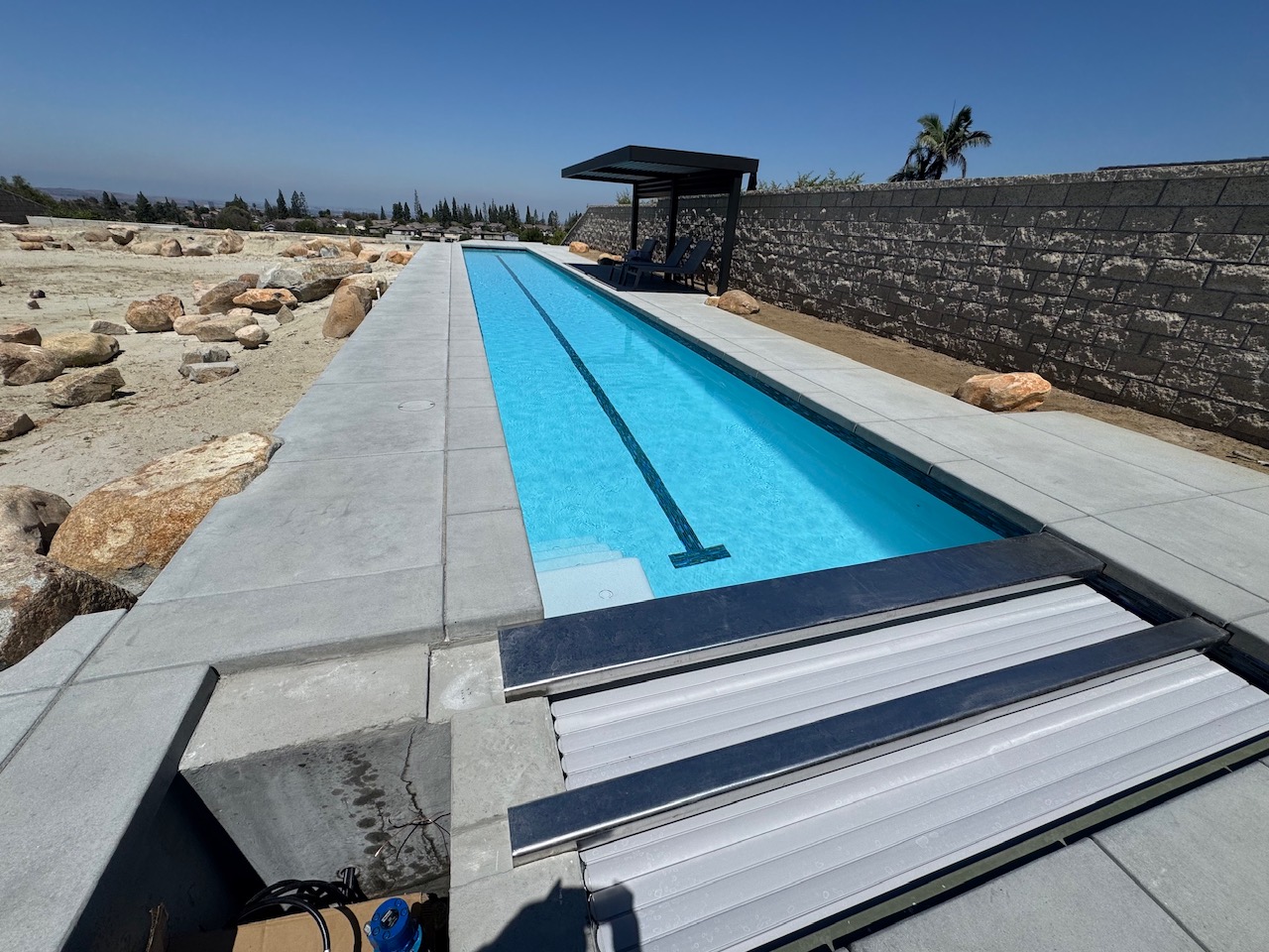
A 75-foot lap pool can look deceptively simple. In this case, however, the sparse aesthetics of the finished watershape concealed an unusually sophisticated hydraulic and water-treatment system. For Tim Smith, the project became an exercise in precision, flexibility and serviceability, driven by a technically demanding homeowner who wanted to understand every component and every decision.
By Tim Smith
My background in the pool and spa industry began on the technical side. I had spent years performing hot tub repairs, equipment evaluations, leak repairs and pool repairs for several manufacturers. Over time, I became increasingly interested in the systems behind the problems I was being asked to solve, particularly hydraulics.
The turning point came through Sean Cassady of Aqua-link Pools, who I met through my brother Cannon Smith. Sean introduced me to a larger project and to a different way of looking at watershaping. Aqua-link was responsible for the structural portion of this project, including the excavation and shotcrete, while my role centered on plumbing, hydraulics, and equipment.
I was immediately attracted to the challenge. At that point, I was already taking Watershape University classes, and this project became a major catalyst for continuing that education. I was learning how to approach watershapes as integrated systems rather than simply collections of equipment connected by pipe.
That distinction became critical on this project, and in my overall professional direction.
Simple Geometry, Complex Hydraulics
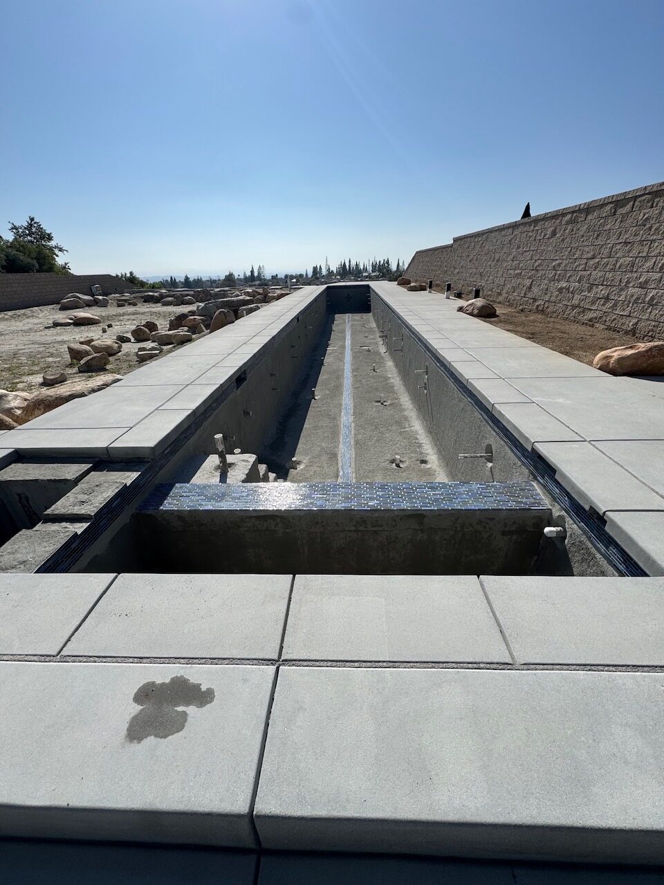
The pool itself was straightforward in appearance: approximately 75 feet long and 10 feet wide, a classic lap pool, with depths roughly four feet at the shallow ends and about four-and-a-half feet in the center. The approximately 22,000-gallon pool was finished in white Eco-finish and designed primarily as a private exercise pool.
But the geometry presented a hydraulic challenge. A 75-foot-long vessel gives you considerable distance over which to distribute water, and the homeowner was determined to take advantage of that.
The original concept was relatively conventional, with three pumps and basic filtration. As the project developed, however, the hydraulic strategy became substantially more sophisticated. The final system incorporated four Venturi skimmers, multiple hydraulic circuits, two filters using glass media, an ozone treatment system, chemical automation, CO2, an in-floor cleaning system and a total of 52 return points.
The objective was not simply to move water. It was also to control where that water moved and under what operating conditions.
The homeowner wanted the ability to alter return distribution according to prevailing winds, operating conditions and desired circulation patterns. Instead of concentrating returns in one area, the system could redirect flow between the right and left sides of the pool. The goal was consistent distribution throughout the water column while maintaining appropriate flow and velocity. That required thinking about the pool as a hydraulic system rather than as a series of isolated plumbing runs. Everything had to be calculated. There was very little room for guesswork.
Designing Around Distribution
One of the unusual aspects of the system was the number of possible circulation configurations.
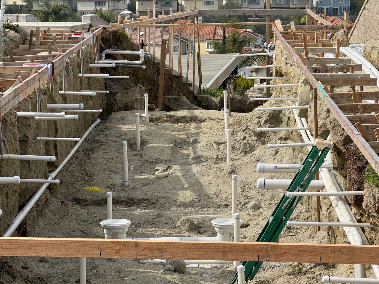
With 52 returns, the system provides considerable flexibility. Technically, the returns can operate simultaneously, although the actual flow delivered to each return depends upon which hydraulic circuit is operating and how the three pumps are being used. The intent was not necessarily to operate every return at maximum flow simultaneously. Instead, the system was designed around multiple operating scenarios that could distribute water differently throughout the pool.
That distinction is important. The objective was to maintain the required gallons per minute and velocity while changing the distribution of that flow. By directing water to different areas of the pool, the system could address prevailing wind conditions and help maintain suspended contaminants in the circulation stream so filtration and chemical treatment could perform more effectively.
The long, narrow configuration also influenced the decision to use manifolds rather than a continuous loop. A loop would have required carrying plumbing approximately 100 feet from one end to the other, adding substantial pipe length and associated hydraulic resistance. Instead, the pool was divided into right and left hydraulic zones and manifolded accordingly.
That approach also applied to the suction system. The physical relationship between the pool, equipment room and surrounding landscape required thoughtful planning to land particular circuits where needed for a clean layout. In several locations, plumbing had to travel down a wall, across the equipment-room floor and back up another wall to reach the opposite side of the pool. Every additional fitting and length of pipe had to be considered.
For me, the objective was always the same: high performance without unnecessarily increasing head pressure.
The In-Floor System
The in-floor cleaning system was another major addition to the project. The system ultimately incorporated 28 Paramount cleaning heads, with the hydraulic design developed in coordination with the manufacturer.
An in-floor system requires considerably more planning than simply placing cleaning heads around a pool. Flow requirements, pipe sizing, velocity, head loss, manifold configuration and head locations all have to be considered before construction.
On this project, placement accuracy was especially important. The homeowner had established an unusually demanding tolerance for the work. He expected measurements and plumbing layout to be accurate to within approximately one-quarter inch. That requirement changed the way the work was approached.
The location of every fitting and every pipe run had to be established before installation. The system had to be laid out precisely enough that the plumbing would arrive at each cleaning head at the intended location.
The result was a system that did more than clean the floor. The extensive distribution provided by the in-floor system contributed significantly to overall circulation. The manufacturer representative who inspected the completed system commented on the amount of circulation being generated. For a project where water quality was a primary concern, that additional circulation was an important benefit.
Water Treatment at the Extreme
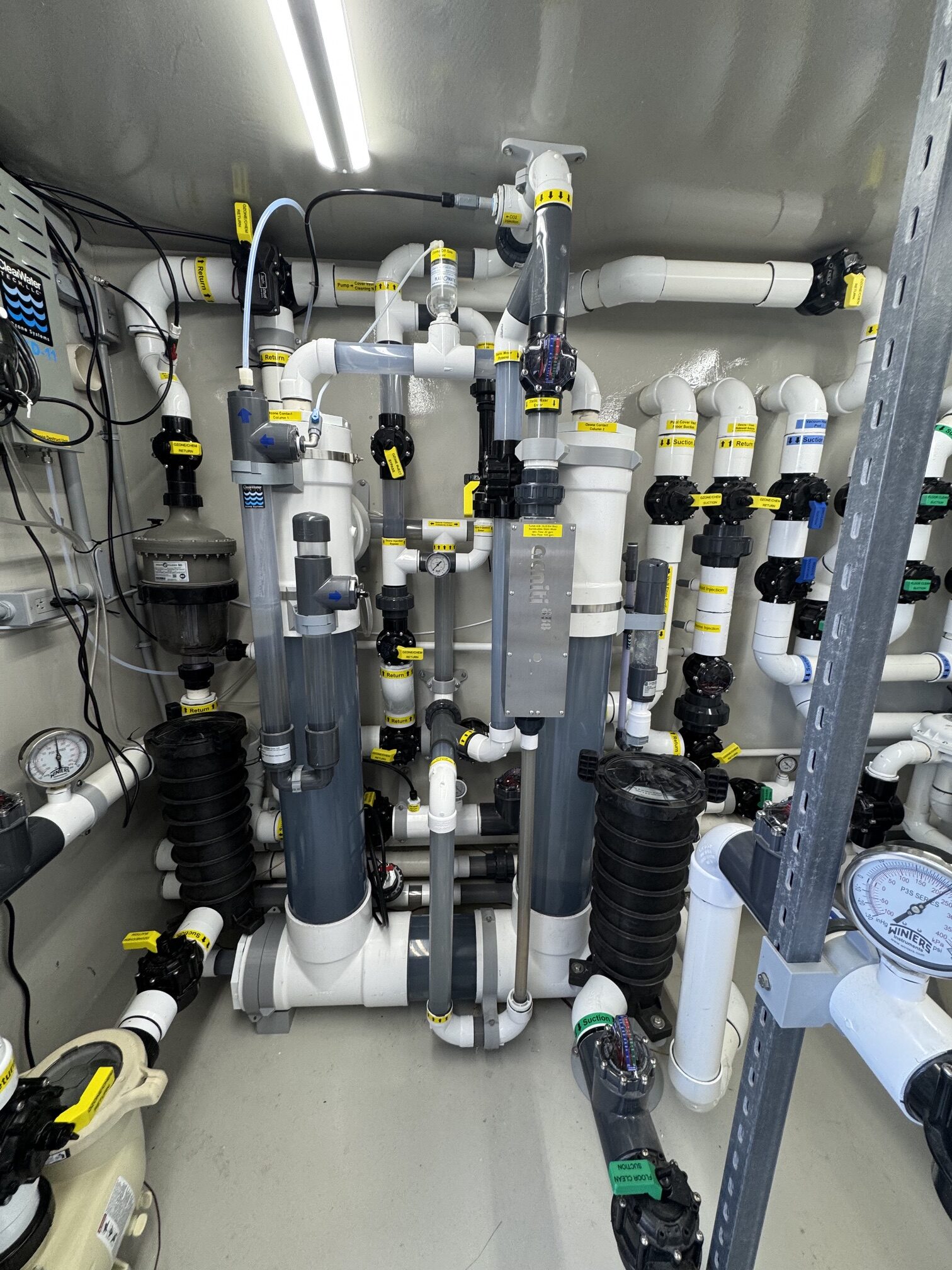
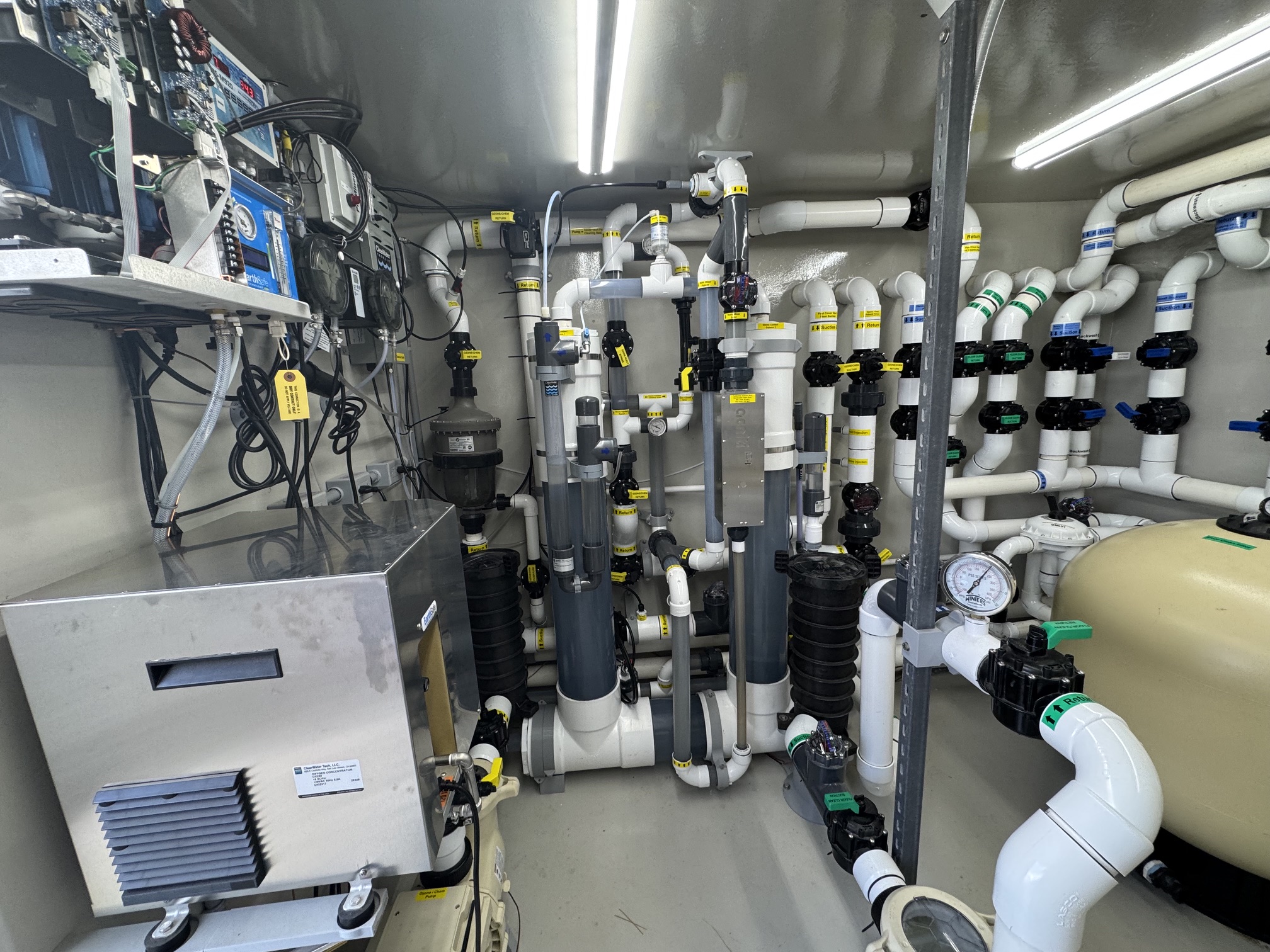
The water-treatment system evolved considerably during construction. The final configuration included an oversized ozone system capable of producing approximately 30 grams per hour, an oxygen concentrator, a Mazzei injector, an ozone contact system and ozone destruct equipment. The system also incorporated CO2, acid feed, chlorine feed and ORP-based control.
The ozone system was intentionally oversized relative to the pool’s relatively modest bather load. The homeowner’s philosophy was to make ozone the primary treatment technology and minimize reliance on chlorine. The system’s capacity allowed the ozone production rate to be reduced to match actual demand.
The ozone injection system was also engineered with considerable attention to gas transfer. Pressurized oxygen from the concentrator feeds the ozone generator, after which the ozone-rich gas is introduced through a custom Mazzei injector manifold with pressure differential gauges and flow control valves. The injector creates suction while the pressurized gas supply increases the amount of ozone being introduced into the water.
The system was further refined around the contact process with dual contact tanks and a nano-bubble system to emphasize gas-to-water contact.
Circulation Through the Cover Vault
The floating cover introduced another hydraulic consideration. Rather than treating the cover vault as a passive space, the system incorporated debris collection and circulation through the vault. Water from the cover area was drawn into the chemical-treatment circuit and returned through six jets positioned along the lower side of the pool.
The returns were arranged at staggered elevations. The treated water was introduced at the lower elevation and then allowed to move back toward the cover vault, passing over the dam wall. This created circulation through the vault and helped keep the cover area cleaner.
That kind of detail characterized the project as a whole. Nothing was considered in isolation.
The Equipment Room
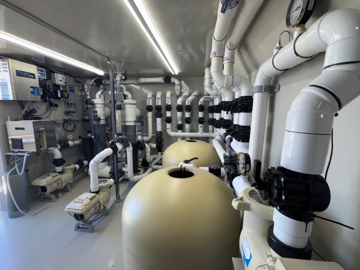
The equipment room is effectively hidden beneath the pool deck. From the far end of the pool, a staircase leads down into the equipment area, which was excavated into the hillside. The arrangement allowed the project to retain the usable yard above while placing the mechanical systems below the pool.
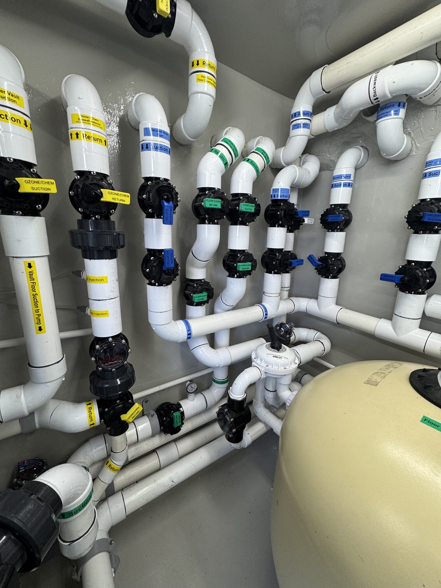
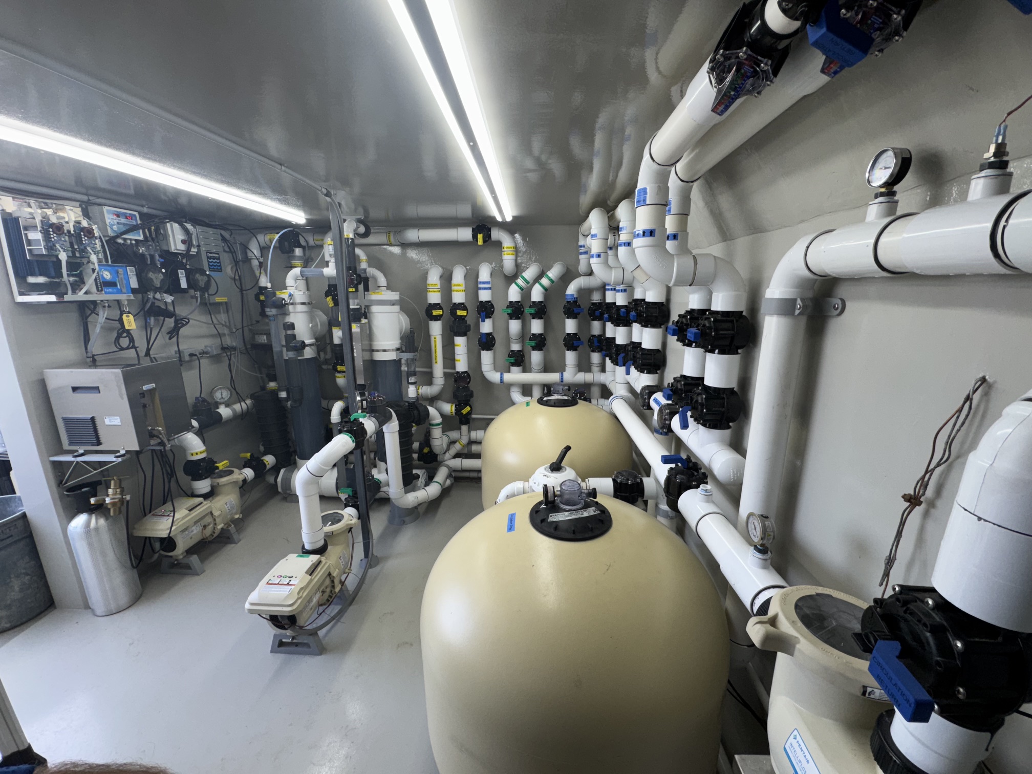
The room is approximately 15 by 15 feet and was designed as a true working environment rather than simply an equipment pad enclosed by walls. It has lighting, ventilation and a durable epoxy finish on the walls, floor and ceiling. The equipment was arranged for access and service, with enough working space to perform maintenance without dismantling the system.
The layout became one of the most time-consuming parts of the project.
The original plans showed a relatively simple equipment arrangement. As the hydraulic strategy evolved, however, the function of individual circuits changed. Equipment locations had to be reconsidered to accommodate those changes without creating unnecessary pipe crossings, additional fittings or excessive head loss.
The final layout was the result of extensive collaboration with the homeowner, my son Adam and myself.. There were numerous iterations of equipment placement and plumbing routing before the final arrangement was established.
My priorities were straightforward:
- Make the system function properly.
- Keep head pressure under control.
- Make everything serviceable.
- Make the equipment room look as carefully constructed as the pool itself.
The homeowner wanted the plumbing installation to be clean enough that it did not need to be hidden. That meant the plumbing itself had to be the finished product.
A Client Who Read the Manuals
The homeowner’s technical involvement had a significant influence on the project.
He comes from a technical background and approached the pool accordingly. He routinely read the manuals for the equipment being installed and would arrive on site with questions about what was scheduled to happen that day.
If we were programming a pump, he had read about the programming. If we were discussing the Pentair IntelliCenter controls, he had studied the controls. If we were talking about PVC, drainage or ventilation, he had researched those subjects as well.
That created an unusual dynamic on the job. It forced me to stay ahead of the project technically and be prepared to explain why a particular approach was being used.
In many projects, the contractor is expected to provide the answers. Here, the homeowner wanted to understand the questions as well. That level of engagement was demanding, but it also made the project more rewarding because there was a genuine appreciation for the technical work and attention to detail.
Technology With a Purpose
The finished pool does not immediately reveal the complexity beneath its simple appearance.
No elaborate architectural details are competing for attention. The pool is long, narrow, and visually restrained. The surrounding landscape has a relatively natural, Zen-garden character, with extensive hardscape and planted areas rather than a large conventional lawn.
The sophistication is underground. It is in the hydraulic balancing, the manifold configuration, the 52 return points, the Venturi skimmers, the 28 in-floor cleaning heads, the ozone injection system, the chemical-treatment circuits, and the equipment-room layout.
For me, that is what made the project significant. Technology is valuable when it solves a problem. It is even more valuable when the system is designed so that the technology works together as a coherent whole.
This project demanded that approach from the beginning. It also reinforced something I had learned through service work: the best way to understand a watershape is to understand why every component is there.
The technical demands of this pool pushed me to continue my education through Watershape University.
Today, I am only a couple of classes away from completing my IWI work, which I’m looking to complete this December at WU’s Fall Session in San Diego. That progression can be traced directly to this project. It began with a long, relatively simple-looking lap pool. Underneath it was a system that demanded precision to the quarter inch.
Tim Smith is owner of Pool and Spa Innovations in Huntington Beach, CA. With 30 years of industry experience, he specializes in residential and commercial pool constructions, renovation, advanced hydraulic systems, and water treatment technologies. His work emphasizes innovative engineering, precision craftsmanship, and long-term performance.