


Toward a Standard


I think we can all agree that design communication between architects, engineers, designers and contractors should be clear and concise. If that’s the case, it follows that plans and other construction documents should be uniform in their organization and layout – in other words, that they should follow a set of standards to which everyone in the design/construction community can and will adhere.
Why the bother? The plain fact is that any given project involves a cast of characters that will be different – sometimes completely so – from just about any other project. This is why I’m such a strong advocate for standards that set minimum criteria and can also be used to develop a level of uniformity that leads to organization, consistency and repeatability.
From trade to trade and project to project, everyone involved in design and construction should be able to anticipate and rely on the organization of any set of plans that might be dropped on the table. Achieving this level of efficiency requires that the sheets are consistently ordered and that the data on those sheets is set forth in repeatable, recognizable and shared patterns.
The goal is quite direct: Not only does uniformity make project coordination easier and more accurate, but it also reduces errors and omissions when contractors are bidding and building the project.
In my first article about the National CAD Standard (NCS) in “Playing by Rules” (WaterShapes, December 2007, page 48), I outlined the ten modules (or chapters) in the NCS. This time, we’ll focus on Module 2 on Drawing Set Organization and Module 3 on Sheet Organization. (Both of these chapters are part of the Uniform Drawing System established by the Construction Specifications Institute and have been incorporated into NCS versions 3.1 and 4.0.)
As declared in my December article, my intention here is not to address every detail of the NCS or these two modules; rather, I seek to bring greater awareness of the NCS to a watershaping industry that stands to benefit from getting engaged with the standards movement.
SET ORGANIZATION
Let’s cut right to the heart of the uniformity goal, which is about identifying every sheet in a set of plans with a coordinating sheet number and then organizing all those sheets in a specific sequence.
As we covered in my December article, the NCS standardizes sheet numbering using the scheme DM-TSS, where D is the Discipline Designator, M is the Modifier Character, T is the Sheet Type Number, and SS is a two-digit sheet numbering sequence starting with 01 and rolling on to a potential limit of 99.
All of this was defined in some detail in that article, where we identified Discipline Designators and suggested that the letter “W” be used to indicate all watershape plans – even if they contain only sheets of interest to specific disciplines (such as structural engineers or electricians).
That proposal came in the context of layer name prefixes we use in designing within CAD environments; now what we’re doing is extending that concept to the sheet numbering scheme as a way to distinguish our plans from those of landscape architects and others.
The Modifier Character, M, may be used to divide the discipline into logical divisions (such as a specific trade). For example, if you have a sheet that is dedicated to plumbing, the modifier character “P” could be used. In practice, however, I find that in organizing our sheets, seldom is one trade so specifically isolated: As a result, we never have occasion to use a Modifier Character.
The Sheet Type Number is separated from the Discipline Designator by a hyphen and organizes the sheets into the following groups: 0 = General (symbols legend, notes and the like); 1 = Plans (horizontal views); 2 = Elevations (vertical views); 3 = Sections (sectional views, wall sections); 4 = Large Scale Views (plans, elevations, stair sections, or sections that are not details); 5 = Details; 6 = Schedules and Diagrams; 7 = User Defined (for items that do not fall into other categories); 8 = User Defined (for additional items that do not fall into other categories); 9 = Three-Dimensional Representations (isometrics, perspectives, photographs).
The Sheet Sequence Number starts with 01 for each of the Sheet Type Numbers listed above. Additional slicing of the Sheet Sequence Number can be used to organize sheets with additional logic: If, for example, the project has multiple levels, the first-floor plans could be on sheet X-X11, while second-floor plans could be on sheet X-X21.
Putting it all together, a common sheet number will be W-111, which is a Watershape Plan/Plan View/First Floor/First Sheet. Where possible, sheet W-111 should align with plans prepared by other trades showing the same area. Thus, if the landscape plans include an L-111 sheet for the front yard with a fountain and an L-112 sheet for the rear yard with a pool, it makes sense that the watershape plans would be logically labeled W-111 for the fountain and W-112 for the pool.
ASSEMBLING THE PUZZLE
Let’s back up just a bit so we can put the example discussed just above into a fuller context.
Table I (below) is a copy of one of our typical Sheet Indexes – an excerpt from our Title Sheet W-001. This is something that can be set up for each project by adding or deleting sheet references as needed, but the overall sequence of the sheets never changes, and repeat clients and contractors have let us know they appreciate that consistency from project to project. (The empty boxes on the right, by the way, are reserved “for office use only.” We generally use them as check boxes or as small fields for handwritten notes made while we finalize and plot the sheets.)
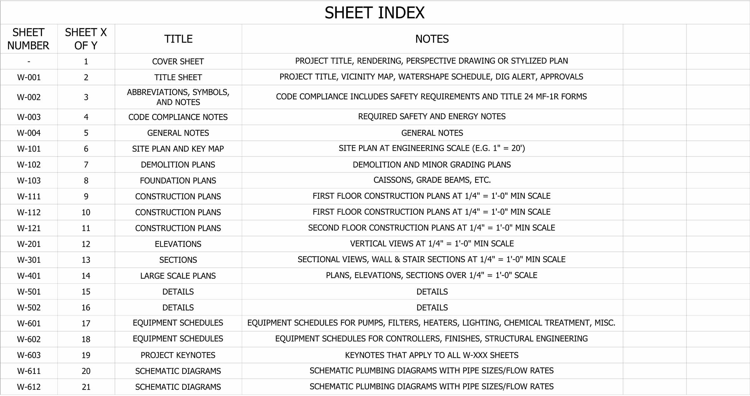
| Table I |
Helpfully, we didn’t have to make this system up. The NCS Drawing Set Organization module includes sections on file naming, file management, archiving, and sheet-number suffixes used for project phasing (and for major revisions where a whole sheet is revised rather than carried forward as a revision-clouded section). There are good schemes for these items, but in our own practice we rarely use project phasing, and, frankly, our file organization/naming schemes are simpler than NCS models because of the way we structure our plans.
No matter what you do, the key is to keep things simple, organized, reasonably compliant with NCS and consistent. Also please note as well that the sheet numbering scheme is definitely something that can (and should) be implemented by hand drafters as well as CAD users.
Except for small projects, the simple fact is that plans are rarely completed by only one entity. Many of our projects include an architect, a landscape architect, a structural engineer, a geotechnical engineer and representatives of various related trades. If each of us developed his or her plans in a personal vacuum with no set of organizing principles, the resulting pile of plans would be difficult to coordinate – and our projects even more difficult to build in the field.
By contrast, when a watershaper develops a set of plans that are properly organized and labeled according to a common standard, it can readily be merged into a grander set of project plans as developed by the design team.
As you might imagine, the NCS defines the logical sequence in which all the sheets should ultimately be bound. The complete set starts with general sheets that include items applicable to all disciplines (safety, for example, or a requirement to schedule work around a specific bird migration).
That’s followed by big picture items such as site maps with property boundaries; grading plans, utilities and other items ordered within the set as well. Then come watershapes and landscaping, which are next because they complete the exterior work. After that you’ll find sheets for a sequence of disciplines including architectural, plumbing, mechanical and electrical plans – and others for separate structures.
DIGGING DEEPER
This sequence of plans is carefully ordered so that big items (such as grading) appear in the beginning of the set, with more and more detail added in subsequent sections.
According to the NCS, the key disciplines should be organized into the following sequence after the Cover Sheet: G = General; H = Hazardous Materials; V = Survey/Mapping; B = Geotechnical; W = Civil Works (or, for our purposes, Watershaping); C = Civil; L = Landscape; S = Structural; A = Architectural; I = Interiors. (This list continues to include other trades as well, but you get the idea.)
|
Get Your Copy The National CAD Standard (NCS) can be purchased from a number of online stores, including those sponsored by the National Institute of Building Sciences (NIBS), the American Institute of Architects (AIA) and the Construction Specifications Institute (CSI). The price went up with the new Version 4.0 and is now $410 (with generous discounts for NIBS, AIA or CSI members. Balancing the extra cost is the fact that the new version includes symbols in a CAD format so you don’t need to draw them yourself – a considerable time/effort savings. D.P. |
As mentioned in the first article and reiterated above, I do not recommend trying to split up a set of watershape plans into the individual disciplines listed above. It would be too confusing for, say, a project electrician to get involved in the electrical work that falls under the purview of the watershape contractor.
Indeed, the only time our sheets do not include the W prefix is when we are designing an integral architectural element (such as an outdoor kitchen/living room) as part of the design. In that case, it usually makes sense to use the Discipline Designator A to isolate the building design from the watershape design. Where we use this approach, it helps as well with permitting and division of the scope of work amongst multiple contractors.
Now that we’ve run through the basics of sheet numbering and drawing sequencing as keys to uniformity, let’s take a look at the sheets themselves and the Sheet Organization Module of the NCS.
As you should know if you work much with plans, there are many sheet sizes available for drawing. If you are not using 24-by-36-inch sheets at least, it’s time to step up: Construction plans should be drawn to a minimum scale of one-quarter-inch to a foot. At that scale, it is impossible to show most watershapes on anything but Architectural D-size sheets that measure 24 by 36 inches. (In commercial work, the sheets get even larger: Some require the use of Architectural E-size sheets at 36 by 48 inches – or even Architectural F-size sheets at 30 by 42 inches.)
For quick sketches and study drawings, of course, we’ll use 11-by-17- or 18-by-24- inch sheets, but these will be later photocopied, scanned, or redrawn onto larger sheets before they leave our office.
As a matter of uniformity as well as utility, it’s important that all sheets in a full set of plans are the same size, which is why, whenever we’re starting on a project, we always ask the team leader (usually the architect) what to use. If it’s left up to me to make the call, we’ll use Architectural D-size sheets: They’re much more manageable than larger sheets, and we wouldn’t use anything smaller.
PAPER CHASE
It should also be mentioned (since nothing is ever quite as simple as it should be) that there are different standards for sheet sizes.
ANSI, for example, also marks their sizes with the letters A-E, with the indicated sizes being multiples of a standard 8-1/2-by-11-inch base (that is, ANSI’s D size is 22-by-34 inches – the equivalent of eight sheets of 8-1/2-by-11-inch paper). Although ANSI-compliant paper is readily available in the United States, the additional two-inch gain in length and width of paper has made using the “Architectural D-size” standard a general preference.
And if you work in Europe or Asia, you need to concern yourself with the ISO standard. In those places, the sheets marked A1 are, at 23.4 by 33.1 inches, as close as you’ll come to the Architectural D-size sheets found in the United States.
Once the sheet size is selected, it’s time to divide the page into two major sections – one for the title block and the other for the drawing area. (The NCS also identifies a “production data area” – basically a timestamp with a filename and plotting date information – that is usually located beyond the drawing limits on the left side of the sheet. This can be useful but is not required for CAD-based operations – and is never used by hand-drafters.) With that one minor (and optional) intrusion, the drawing area is basically everything outside the title block.
To help organize the drawing information, the NCS defines a grid system in which sheet notes are usually located on the right-most column and drawing blocks are somewhat aligned with the grid to help organize the sheet (as needed). A freeform pool will not usually benefit from this gridwork, but equipment schedules, details and elevations are often helped by the structure whether the grid is visible or not. (We’ll get into equipment schedules and details in future articles.)
From an organizational perspective, title blocks are every bit as important as the information in the drawing area. Everyone must look there for important project information and specific sheet-related information such as the revision history.
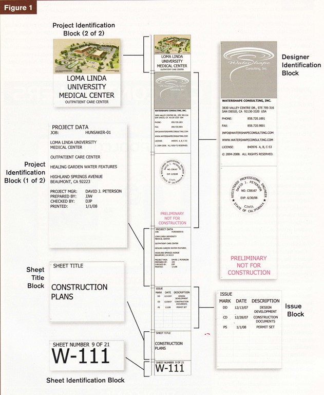
In the title block shown in Figure 1 (below), for example, the Project Identification Block provides key project information including the project name, owner identification, the address of the project, a legal description and other data. In this case, we inserted a color copy of a rendering by the architects. When an identifiable project image isn’t available, we’ll supplement a project logo with a very large single character such as S to identify a “Smith Residence” project.
The rationale for including our logo is straightforward: It helps anyone quickly identify our sheets from the hundreds of other sheets floating around an office. We include a project drawing or identifying mark for the same reason: When I reach into the back seat of my truck, I can sort more quickly through a pile of plans if all I need to do is look at that top corner.
The NCS also defines a Management Block to enable the designer to list key information such as the drafter’s name, the CAD filename, the project number and more. We usually just include such information in the Project Identification Block (as shown in Figure 1).
MAKING SENSE
In actuality, the title block is a trove of useful information. Of special value is the Issue Block, which supplies the revision history of the project and each sheet: Indeed, once a project has started construction, this is usually the most important field in the title block.
Tying things together, the last two fields are for the Sheet Title and the Sheet Identification Number. The sheet number in Figure 1 is W-111 – the one described above in our discussion of the Drawing Set Organization module. It should be noted that the sheet identification is always at the bottom right corner.
In general, the ordering of the depicted title block matches the setup promoted in the NCS. The exact layout is flexible, because there is no law or other requirement that mandates full compliance with the NCS, but as a matter of practical necessity (and once again in the name of uniformity), I’d strongly recommend orienting the title block vertically on the right side of the sheet so that it is fully visible when the drawings are rolled up.
It’s also useful to note that these recommendations may be used whether you are designing in CAD or by hand. The uniformity provided by implementing these standards will improve the clarity of everyone’s drawings and make developing and executing them more efficient.
Indeed, for anyone serious about their construction drawings, I strongly recommend purchasing a copy of the standard: There’s much more to it than could ever be covered in an introductory column such as this one.
Next: Schedules (tables of information) and drafting conventions (symbology, scale, dimensions and more).
Dave Peterson is president of Watershape Consulting of San Diego, Calif. He’s been part of the watershaping industry since 1994, starting his own firm in 2004 after stints with an aquatic-engineering firm and a manufacturer. A registered civil engineer, he now supports other watershape professionals worldwide with design, engineering and construction-management services and may be reached via his web site, www.watershapeconsulting.com.