Precision on Deck
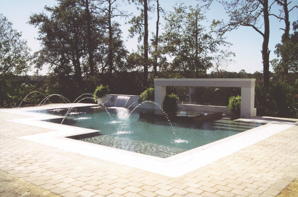
The consumer’s appetite for beautiful water and creative watershape design has grown by leaps and bounds in recent years – and expectations, it seems, are rising right along with the hunger for exceptional details and impressions.
Perimeter-overflow pools and basins are what an increasing number of consumers are after these days, and there’s special interest in what are called “wet-edge applications,” where the water rises to deck level and flows into a channel slot at the back edge of the coping. It’s an amazing look – and harder to accomplish than just about any other because of the precision and tight tolerances required to make it work.
These wet-edge projects involve two substantial challenges for the builder: getting the construction details just right so the water can flow where it needs to flow, and getting the hydraulics just right so that when the water flows, it does so in such a way that the system keeps on working.
There is not much a manufacturer can do to relieve the contractor of the burden of nailing the lines and elevations: If the deck isn’t right on the money, there will be dry spots and disappointment. But there is a new turnkey system that takes away any doubts about the hydraulic end of the project. It’s called Edge Control, developed by the engineering team at Polaris Water Designs in Vista, California.
SYSTEM BASICS
The Edge Control system is a pre-engineered, prefabricated system for the control of water on wet-edge applications. Each system is tailored to fit a specific installation, which means that before the system arrives on site, the manufacturer’s technical services staff has gone through all the calculations having to do with sizing, configuration, flow characteristics, surge capacity, water leveling and more.
In essence, Polaris tackles the engineering of this portion of the project and supports the work on site. The ambition is to make a spectacular water effect available to the full range of watershapers and their clients.
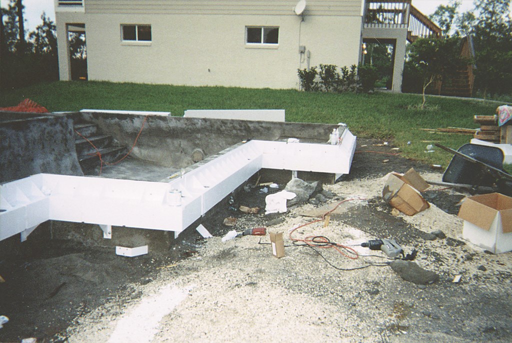
System components are made from lightweight, durable ABS plastic. As the accompanying step-by-step photographs show, prefabricated channels are mounted on the outside of the pool wall after the shell has been shot (which means the surrounding area will need to be over-excavated). The plumbing is attached to a reservoir tank that is used to handle surge capacity and feed the water-leveling system.
When the builder and client have settled on a design that includes a wet edge, the watershaper submits detailed design specifications with the order. Costs will vary depending upon linear footage, straight sections, curved sections, corners, clean outs and reservoir capacity (calculated using the surface area of the pool). Final measurements are taken after the shell has been shot to ensure a precise fit – at which point the system is manufactured.
Once all the components come together, the factory marks each component for easy reassembly. Then the components are packaged and shipped to the job site with a clear set of drawings and written instructions. Under the supervision of a Polaris technical representative, the on-site installation begins:
A Clean Shell
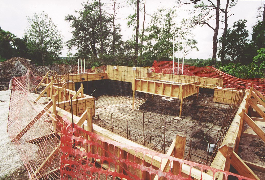
The most important step of the installation process is the preparation of the pool wall. The exterior must be straight and plumb for the vertical distance of 24 to 30 inches where the Edge Control channel will be located.
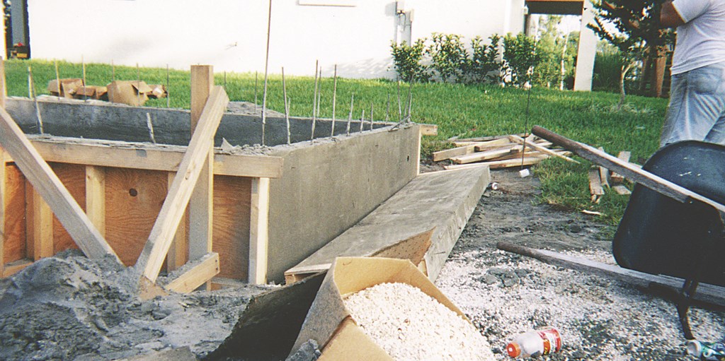
The manufacturer recommends panel-forming the walls using two-by-fours and half-inch plywood, assembling the panels with stainless steel screws and angle plates (left). The importance of nailing down the dimensions at the forming stage – and especially of creating level and square surfaces on the outside of the pool shell (right) – cannot be overemphasized.
Precise Dimensions
Even with the best sort of effort in forming and shooting the shell, there will almost certainly be minor imperfections. That in mind, Polaris recommends taking point-to-point measurements to determine precise dimensions of the shell once it has been shot. It is particularly important to pay special attention to corners, checking them to make sure that they are the exact angle shown on the plans.
If the shell deviates slightly from the original measurements, minor adjustments can be accommodated with this system if the contractor provides an exact template of the off-kilter corners and/or edge contours. If radius corners are involved, a full template that shows the exact point where the curve straightens out is needed.
Level Channels
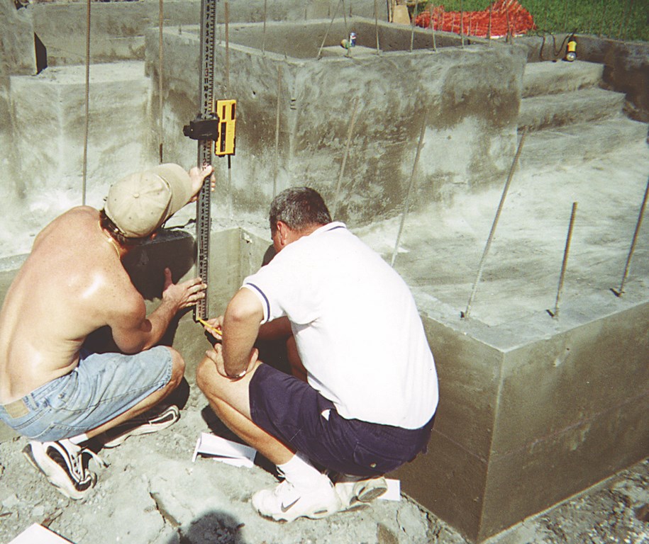
The next step in the process involves determining the elevation of the channel system, which may vary a bit depending on the application. The manufacturer provides a layout drawing with linear and vertical dimensions to guide the contractor through the process.
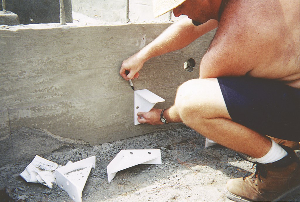
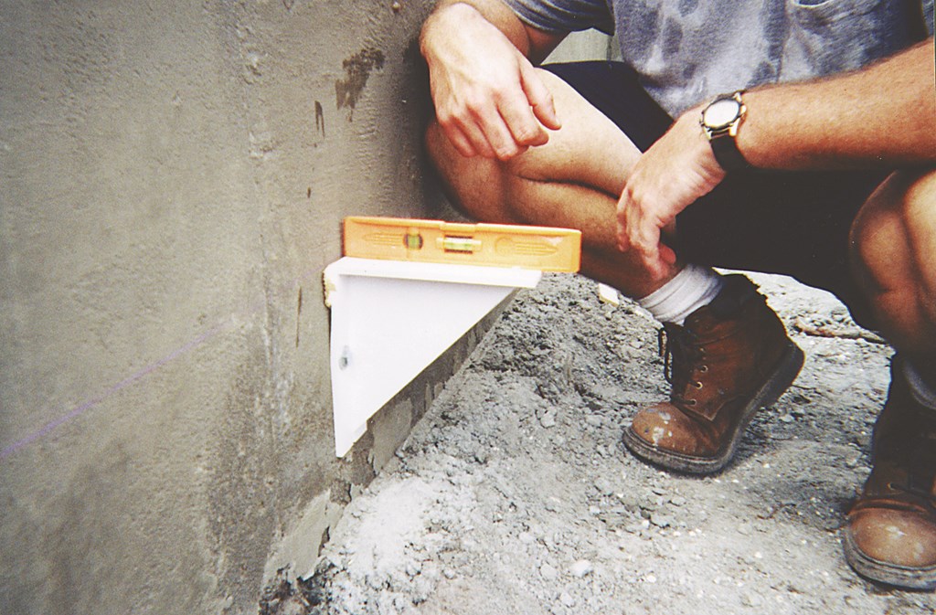
Once the elevations have been determined and marked with a chalk line (left), the channel support brackets are positioned and bolted to the side of the shell (middle). It is critical to check and recheck the brackets to ensure that they are absolutely level in both directions (right). Shim them up as necessary.
Snap Together
Starting at one end, the contractor places the channel pieces on the bracket and fits them together as shown on the layout provided (left). (Slight adjustments can be made at this point by cutting the lengths with a circular saw.)
Once the assembly is complete, the units are glued together using a paintbrush applicator. With the unit assembled and in place, it’s recommended that the builder recheck the level of the unit using a site level or laser level.
Once the checking is complete (right), the contractor applies a bead of Pressure Seal 34 between the top of the Edge Control “neck” and the coping or finished beam to provide a watertight seal. At this point, it is a good idea to test the system by filling it with water to check for leaks.
In the Tank
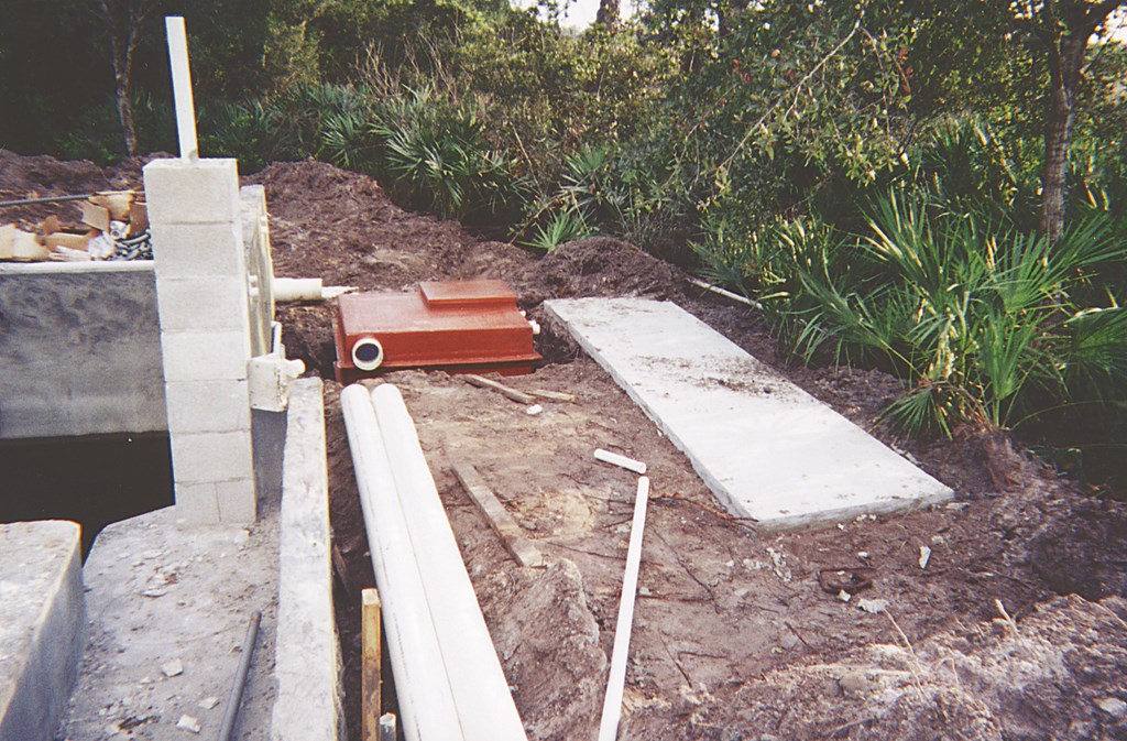
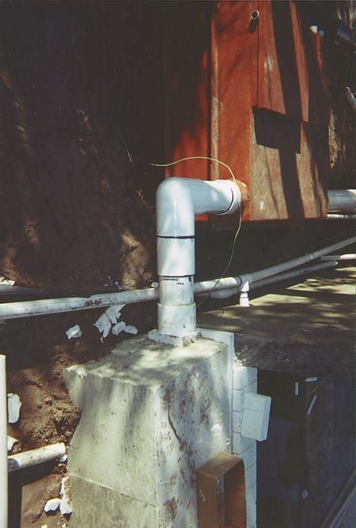
As is the case with most other edge-flow systems, Edge Control requires a reservoir (left) to allow for surge collection, water-level control and proper pump function.
It’s recommended that the positioning of the tank be close to the pool equipment and that a 6-inch pipe be run between the channel and the tank (right). The connection between the reservoir tank and the channel must be level for optimum hydraulic performance.
A Strip of Decking
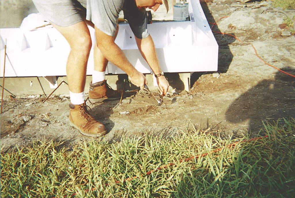
On the project pictured here, the contractor has installed a two-foot-wide deck around the edge of the pool. Rebar was tied into the shell and bent up and around the channel system to provide a steel armature for the decking (left).
In this case, the deck was formed using panels similar to those used on the pool shell (middle). After the deck was poured, the forms were stripped and the area adjacent to the deck was backfilled (right).
Almost Out of Sight
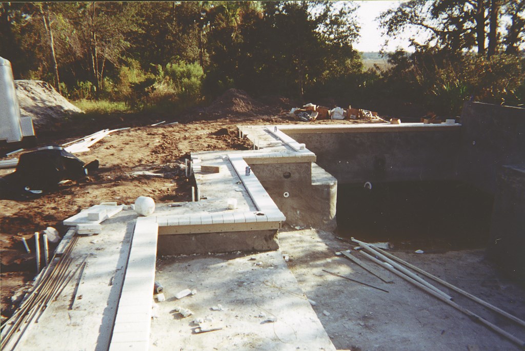
Here the deck has been poured and the coping is being installed.
Only a narrow slot behind the coping stones reveals the presence of the Edge Control system and the job is ready for finishing.
Doug Ruthenberg is general manager of Polaris Water Designs, a division of Polaris Pool Systems of Vista, Calif. He has been involved in the design and construction of swimming pools and spas for more than 30 years and has, for the past 9 years, designed and built waterfeatures for a variety of commercial and residential clients. Most recently, Ruthenberg developed the Edge Control system as an alternative to traditional gutter designs.


