


Playing by Rules


The most important skill needed by any designer is the ability to communicate clearly.
This skill takes many forms, from verbal descriptions, well-assembled photographs and material samples to graphical depictions of concepts, details, dimensioned layouts and other drawn elements. When a watershaper is pushing design limits, in fact, he or she is often called upon to use all of these communication tools to convey ideas and aspire to offer something unique.
In recent years, computer-aided design (CAD) systems have become increasingly popular as a tool in preparing construction drawings. Combined with the designer’s creativity, these programs assist greatly in the production of plans. Unfortunately, however, our usage of them varies greatly in style and content from project to project and designer to designer. Indeed, these variations can be so radical that some plans are not easily understood by other professionals; moreover, the exchange of electronic CAD files is not always as convenient or efficient as it should be.
This is why a group of industry experts has banded together to create the National CAD Standard (NCS), which is the core subject of this brief series of articles. That effort, which has met
with limited acceptance so far, is in my opinion the key to maintaining the desired clarity of communication designers crave and of which these systems are so fully capable.
WORKING TOGETHER
By intention, the NCS doesn’t aim to curb flexibility or creativity; rather, its purpose is to improve the efficiency of and build consistency into construction drawings while simultaneously minimizing design errors and liability issues that arise from miscommunication.
From the start of the movement in 1997, the NCS has been a collaboration among leading architecture, engineering and construction organizations, all of which recognized a need to establish a common foundation for drawing information. The latest version, NCS 3.1, was released in 2005; Version 4.0 was approved and is scheduled for release in November 2007.
In whole or part, the NCS reflects the published views of such diverse entities as the National Institute of Building Sciences (NIBS), the American Institute of Architects (AIA) and the Construction Specifications Institute (CSI), among others. The group also includes representatives from private architecture, engineering and construction firms as well as software companies that develop and support CAD-related products.
The 960-page standard is divided into several chapters and is available in a PDF format on CD-ROM. This format makes sense because many of the pages are tables of information or defined graphical information that are of limited utility to the typical user; the searchable nature of the CD-ROM enables these users to zero in on subjects without the need to flip through a ream of paper. If there’s one drawback to the disk, it’s that it does not include actual CAD blocks or electronic files, which means the designer is left to set up his or her own drawings.
This is all voluntary: The NCS is not a code that CAD users must follow. Instead, it encompasses a set of recommended practices and graphical approaches built on a consensus of industry leaders. Relatively few design consultants or individual practitioners are following the NCS at this early stage, but we see signs that this may be changing simply as a matter of practical necessity.
Now that it’s available for general use, leading architectural firms are beginning to use the NCS for quality control within their design and engineering teams. Much closer to home, my own firm, Watershape Consulting, Inc., of San Diego, Calif., has recently adopted the standard in almost every aspect of our construction-drawing endeavors, and we’ve already begun reaping the benefits.
EVERYONE WINS
Who should be using the NCS? The simple answer is everyone in the design/engineering/construction world – even those who don’t use CAD. In fact, of the standard’s ten chapters, only two of them offer specific CAD requirements – that is, the CAD Layer Guidelines and the Plotting Guidelines. The other eight sections of the standard can be fully implemented by anyone using pencil on paper.
To be sure, however, the NCS is a work in progress and it is clear that perfection has not yet been attained. Despite these growing pains, it’s flexible guidelines are set up in such a way that designers are free to pick and choose the components they wish to implement. Still, it’s a product of consensus and obviously will not fit every situation or please every watershaper.

| Executing this large, palapa-covered kitchen/dining area was a uniquely complicated process involving several design and construction disciplines. If we hadn’t all been working with a shared, standard approach to CAD representations, there is simply no way we all could have collaborated as effectively as we did without extreme difficulty. |
For that reason, it is not my intention to cover every detail of the NCS in this series of articles, nor is it my intention to teach you all you need to know about the standards. Instead, my aim is to create awareness of the NCS in the watershaping industry and spread the word that it is based on credible input from hundreds of professionals who’ve worked on these guidelines for many years.
Ultimately, it’s my view that implementing the standard in our own practices will help us all become more efficient and professional and that this knowledge will help us establish and maintain our rightful place at the design table with other architecture/engineering/construction professionals. To that end, let’s dig in and take a closer look at one of the prime topics covered in the NCS – that is, the CAD Layer Guidelines.
This chapter in the NCS was developed by the AIA starting in 1990 to improve the interoperability of electronic CAD files – the goal being to standardize the layer-naming scheme and layer contents so that files exchanged between consultants could be efficiently managed. The architects’ association continues to lead in developing these standards, but the NCS also briefly discusses an International Standards Organization (ISO) Standard that suggests a slightly different but compatible scheme in a way that bridges the conceptual gaps.
Before I explain this layering scheme, let me address hand drafters by defining what a layer is. In effect, CAD layers are analogous to those physiology texts where clear sheets of clear plastic are covered with representations of different muscles, organs and bones and are peeled back one by one to get down to the basic structures hidden below. CAD systems are like that, but there are unlimited numbers of available layers for any given drawing – and those layers can be turned on and off in any order at any time.
A LAYERED REALITY
The trouble with these multiple CAD layers is that designers tend to use a lot of them in whatever ways we choose and for our own purposes.
I keep my engineering stamp in a specific layer, for example, that is turned off until the plans are ready for a wet signature. I use other layers to control specific line weights (such as 0.65 mm), colors and screens (such as 25% of black), while others are used to determine which objects are present on a specific sheet (such as a layout plan that includes dimensions but no plumbing or a plumbing plan that includes every pipe but only a few critical dimensions).
On a simple project with only one designer, the specifics of the layering scheme are of little importance, but many of our projects involve multiple consultants. In these cases, frustration develops quickly when another member of the team receives a CAD file via e-mail but can’t figure out how to sort through the layers. And it gets even more confusing when the CAD files link to other poorly organized CAD files.

| On an active screen, the CAD standards guide us to create successive, defined layers in our documentation, with each layer color-coded so that individual details can be worked on separately before changes are reflected throughout all unlocked layers of the document. Once all the involved disciplines have completed their reviews, final construction documents are ready for circulation among building officials, contractors and subcontractors. |
In this real world, for example, it’s not uncommon for us to open a single CAD file from one of our clients and find out that there are four or five other CAD files referenced into the one we’ve opened, everything from a topographical file or architect’s base file to the landscape architect’s base file or a utilities file from the Civil Engineer.
Helpfully, the NCS’s CAD Layer Guidelines organize the layers in two ways, first with specific naming scheme and then with a long list of predefined layer names that follow that naming scheme. In a nutshell, this layer naming scheme is summarized as DO-MAJR-MINR-MINR-S, where D is the Discipline designator, O is the Optional modifier for the discipline designator, MAJR is a Major group, MINR is a Minor groups (either 1 or 2) and S signifies Status.
The discipline designator (D) defines the category of the layer contents using NCS-specified terms. P, for example, designates Plumbing and E indicates Electrical and so on. There is no specific designator as yet for watershapes, perhaps because none was considered but just as likely because the standard writers saw watershaping as being comprised of elements from many different disciplines.
PARSING THE SYSTEM
At this point, I do not recommend that watershapers worry about splitting their construction drawings into those many predefined disciplines, if only to avoid confusion in the permit process and the additional confusion that would arise when the drawings are integrated into larger sets of plans in which other disciplines are addressed by consultants beyond the watershaper’s control.
Instead, allow me to suggest that watershapers take over the letter W as their single discipline designator. It’s already been assigned to “Civil Works” by the NCS, but the standard also uses C for “Civil Engineering” and says the difference is that C applies to projects occurring within a single property boundary while W refers to larger-scale projects such as highways or canals that cross multiple property boundaries.
My thought here is that W would be a safe choice: It would be a rare situation where anyone would use the W designator and even more rare that the same project would include work by a watershaper!
|
Pick Up a Copy The National CAD Standard can be purchased at the online stores of the National Institute of Building Sciences (NIBS – click here), the American Institute of Architects (AIA – click here) and the Construction Specifications Institute (CSI – click here), among others. The cost is approximately $350, but membership in one of the sponsoring organizations will save you about $100. The current standard is Version 3.1; Version 4.0 has been approved and should be available by the time this article reaches print. — D.P. |
There’s also a possibility of lumping watershapes into the L classification, where landscape work is isolated. This makes a certain amount of sense given that most watershapes are considered as landscape components, but in my own experience I’ve seen too much possibility of confusion: Half of my firm’s work is in support of landscape architects on large commercial jobs, and most of them use L as the prefix in their layering schemes. If both landscape architects and watershapers were to use this designator, we could easily lose track of who created the layer and the information.
The next element in the layer name is the Optional modifier. This classification is used to create subcategories in each of the disciplines, including D for “Demolition,” F for “Finishes” and so on. Depending on the specific project, we have used WS to represent “Watershape Structure” and WP to signify our “Watershape Plumbing” layers.
Then comes the Major Group, a four-character field that defines major elements of the project. For example, PLAN is used for floor plans and ESMT represents easements – all quite logical and straightforward. But the NCS is rigid on this point: There are, it states, no user-definable Major Groups, and the designer is strictly limited to use only the predefined groupings. While there are several I personally would like to define, few of the published, allowable terms are used by watershapers. Perhaps this will change in upcoming versions, but for now all we can do is use the Minor Groups to define new categories.
The Minor Group is an optional four-character field used to break down the Major Groups into infinitely categorized layers as needed to organize given sets of drawing layers. In our practice, for example, we use the group POOL to define certain aspects of the pool – as opposed to RTWL for retaining walls and footings. There’s also a second Minor-Group option that lets us get even more specific. We, for example, use BOND to separate bond-beam information from bench information and fully enjoy the degree of flexibility this allows.
Finally, the Status code is an optional character that defines the status of the work or the construction phase for a given layer. There are seven specific letter codes to be used here along with the digits 1-9. The status code F, for example, denotes “Future Work.”
A STRUCTURED APPROACH
To put this pile of information in a practical context, let’s consider the following example of a complete layer name found in our company’s drawings – that is, W-PLAN-POOL-WATR.
When I open a CAD file drawn by one of our designers, I know this layer will have a polyline representing the edges of water for the project’s pools, spas and waterfeatures. I know I can double-click that line to get the perimeter length and surface area with confidence that it is correct.
Now, when the architect or some other member of the design team sends us a revised CAD file and the pool shape has changed, we can quickly validate the accuracy of our plan and its measurements. And when we readjust the pool shape to address a code issue or for structural reasons, the architect can see that change by referencing our CAD file back to their base.
That all may seem complicated, but believe me, the hassles encountered at this level are nothing compared to sorting out the differences, disputes and disagreements when non-standardized plans pass back and forth among members of a design team who each have their own ways of doing things.

| Of all the remarkable things about this project, the one that stands out most is the fact that, once the construction drawings were ready, it was possible for us to build the watershapes at the same time other contractors were working alongside us on site. This level of integration and organization was truly helpful – and it was all made possible by a standardized approach we agreed to use with our CAD files. |
Reaching beyond this layer-naming scheme, the NCS also attempts to list specific layers commonly found in construction drawings. To that end, there are 76 pages of suggested layer names organized by discipline designator, but it’s my sense that few of these will ever be used by most watershapers.
To implement such a system in any CAD-using operation, I suggest that designers who use these systems should spend a couple hours setting up a “starter file” with a base of key layers, defined lineweights and colors so that the layers are consistent from one project to the next. Even this measure of consistency will improve efficiency and drawing accuracy, save time in set-ups and open more time for work that really counts.
In my shop, for example, we recently completed design, engineering and construction for a complicated project that benefited from the exchange of CAD files among many consultants. These plans were complicated: First, the one-acre lot is intersected by deed-restricted zones that could not be touched for environmental-protection reasons. Second, the project called for a large palapa-covered kitchen and dining area that required positional setbacks from the property lines for fire-suppression purposes.
PRACTICAL PROGRESS
Those two governing factors, when combined with many elevation challenges and a need to balance cut-and-fill on the site, made critical collaboration among several disciplines the key to project success. Without a standard approach to CAD representations, my suspicion is that the exchange of information among various consultants would have been extremely burdensome – if not completely impossible.
Our firm handled the grading plans, utility-improvement plans and the design of the palapa and a set of watershapes that included a pool, a spa, a slide, a grotto and a pond beneath the palapa’s deck. All of this was for clients who wanted a backyard that would look like the Grand Wailea Resort on Maui – their favorite vacation destination.
We tackled the design by merging the grading plans we developed with the architect’s house plans and the surveyor’s topographical CAD file, using those background files to analyze views and optimize spatial relationships among key design elements. After establishing a base plan of the watershapes and palapa that included detailed elevations, we forwarded the file to the landscape architect for completion of the design of the surrounding areas. Once he had completed his plans, the files were sent back to us to address minor coordination issues; next, they moved along to the surveyor, who laid out key elements of the yard, and to the landscape contractor, who started at the same time work began on the watershapes and the 10,000-square-foot house.
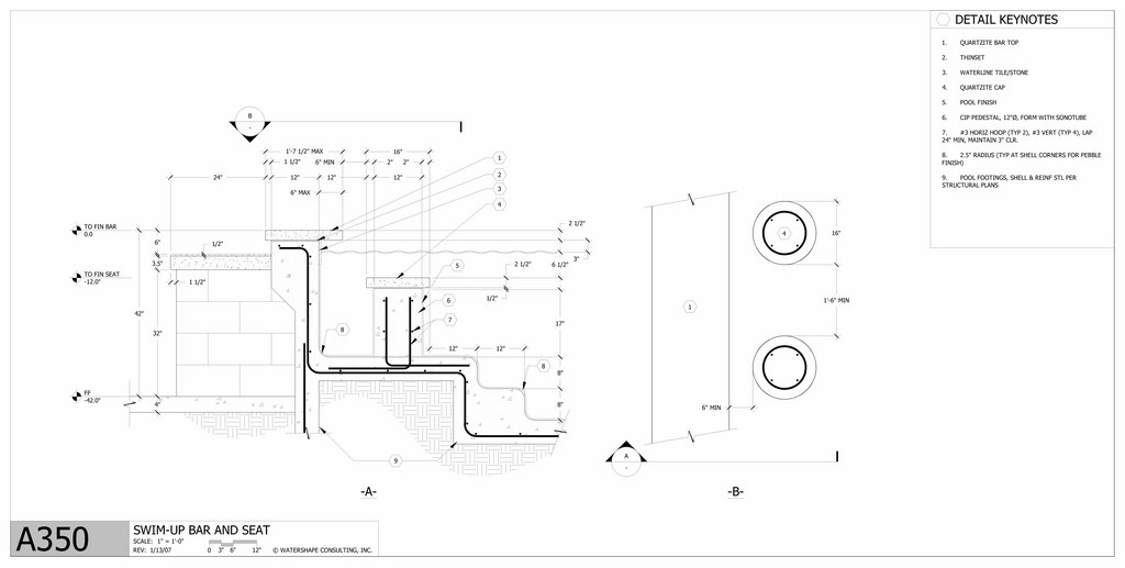
| This detail reveals the way in which we dealt with the various elevations and intersections having to do with the decks, pool, and pond – a remarkably complicated process made much easier by the fact that all of us involved in the project could easily see and accommodate what was happening as the design process moved forward and gained refinement. |
The detail shown in the illustration above ultimately was used to coordinate the many elevations and dimensions that link the pool’s swim-up bar to the kitchen within the palapa – factors that reach far beyond those specific details to influence decking, stairs and positioning of the pond beneath the palapa. (In a future article, I’ll get into specifics of how this sort of detail comes together.)
The result of all this effort was a coordinated set of construction drawings that accurately defined every element so that we could build the pool at the same time the landscape contractor worked on the surrounding areas without any conflicts or coordination problems in the field.
That’s where we’ve found the greatest benefits of standardization: By imposing a truly integrated sense of organization on projects from the planning stage forward, observance of the standards has opened our projects to clear communication and an unmatched level of efficiency in the field, where it matters most.
Next time: We’ll look at two more fundamental components of the NCS – how drawing sheets are indexed and how the information on those sheets is organized using CSI’s Uniform Drawing System.
David Peterson is president of Watershape Consulting of Carlsbad, Calif. He’s been part of the watershaping industry since 1994, when he began working for an engineering firm that specialized in large aquariums and marine-mammal exhibits. In 1998, he stepped onto to manufacturing side of things as vice president of engineering for Polaris Pool Systems, then started his own firm in 2004 to support industry professionals with design, engineering and construction-management services. He earned a BS degree in civil engineering in 1995 from the California State Polytechnic University at San Luis Obispo in 1995 and is a registered civil engineer.