


Motive Power

Designing watershapes of any sort is becoming more and more challenging every day.
Where not all that long ago consumers were happy if a pool or spa or fountain or pond simply looked good and operated reliably, there’s a new generation of consumers who are much more interested in how these vessels are built and, more specifically, in knowing about how energy efficient they are.
This trend is being driven on the one hand by the inevitability of rising utility rates and on the other by legislation such as California’s Appliance Efficiency Code (Title 20) – a rule that’s attracting the attention of code writers across the country because of the overwhelming importance these days of reducing energy consumption.
With that backdrop, this article takes a look at a watershape’s main energy consumer and the most basic of all its
many components – that is, the motor that drives the hydraulic pump and thereby moves water through the system. We’ll start with a look at basic motor types and technologies in this piece; next time, we’ll dig into practical and appropriate applications of these devices.
BASIC PHYSICS
It will come as no surprise to anyone who has read my articles in WaterShapes through the years that I’m a firm believer that equipment choices related to watershapes of all kinds should always be determined by the hydraulic requirements of the job – with an eye, of course, on project economics.
With motors, however, there’s an additional point to be considered: As electrical devices, they are a key determining factor when it comes to a system’s overall energy consumption, meaning we must also consider them in light of the degree of energy reduction we’re trying to achieve for our clients.
To evaluate this point effectively, we need to know something about motor technology, but we also need to be aware of the physics involved in the way motors consume energy and familiar on some level with the Affinity Law, which defines the relationships among the motor shaft’s rotation, the flow of water, head pressure and power consumption.
This Affinity Law is, in fact, the core concept behind the science of motor speed and energy consumption. It states that the relationship between a shaft’s revolutions per minute (rpm) and water flow is uniform – that is, a motor generating a flow of 100 gallons per minute (gpm) 3,450 rpm will generate half that flow (50 gpm) if the shaft’s rate of rotation is reduced by 50 percent to 1,725 rpm.
(It is important, of course, to note that these relationships are theoretical: They do not take motor or pump losses of efficiency into account, but those are topics for a different discussion.)
Continuing with the Affinity Law, the relationship between head and shaft rpm is different: If the motor drops 50 percent from 3,450 to 1,725 rpm, instead of dropping by half (as did flow), pressure actually drops by 75 percent, falling from 60 feet of head all the way down to 15 feet – just a quarter of the original pressure/head relationship.
Where things get truly interesting (at least in discussions of energy efficiency) is that the relationship of shaft rotation to power consumption involves an even more pronounced difference – that is, if the shaft rotation drops from 3,450 to 1,725 rpm, the motor’s energy draw drops to just one-eighth of the original consumption level – a drop of nearly 88 percent! That’s a huge difference, and it’s no wonder we’re all being forced to pay attention to these relationships as never before.
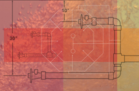
| Figure 1: Charting the Affinity Law for flow vs. rotation speed (left), pressure vs. rotation speed (middle) and power consumption vs. rotation speed (right). (Note: These charts illustrate the Affinity Law as applied to three different sized/horsepower motor/pump combinations.) |
Bottom line, this last relationship is why the industry is pursuing multi- and variable-speed motor technology so diligently: The single-speed pumps we’ve used for generations all turn in a band of rates around 3,450 rpm in the high range of energy consumption, while multi- or variable-speed pumps offer obvious opportunities for energy savings based on the fact that they perform their functions at lower rotational rates. (See Figure 1 for a full charting of the Affinity Law relationships.)
MOTOR TYPES
If you take nothing else from this discussion, it’s that the decisions you make about motors are important – despite the fact that most of us grew up in the industry thinking of them as an adjunct product a supplier attached to the dry end of a pump as interchangeable commodities.
Those days are gone, and if your clients are as interested as I know they are in energy efficiency, you need to apply almost as much care to motor selection as you do to your options among other system components. To arm you with the information you need to make the right choices, let’s review basic motor types and define how they fit into the energy scheme of things.
[ ] Single-speed motors: As mentioned above, these devices have been at the heart of circulation systems as long as there have been water-recirculating vessels, and they remain the most common type of motor used to this day. Nowadays, however, they’re available in two forms: There’s a “standard” model, which is the basic, old-school technology, and a “high-efficiency” model. The latter features a higher “power factor,” using a lower amp draw and thereby creating higher efficiency through lower power consumption: When attached to a pump, in other words, these motors produce more flow in gallons per minute per unit of power consumption.
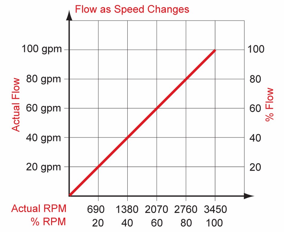
| Figure 2: A typical AC Motor. |
In either form, these motors are still in high use because of their low cost, wide availability and smaller fixed-plumbing sizes – especially in systems where constant-flow requirements make them particularly suitable. They operate at a single rotation speed of around 3,450 rpm and, once the motor gets the attached pump impeller up to speed, maintains that level as long as it draws on an electrical current. That level is called the pump/motor’s operating point – usually somewhere between 3,300 and 3,600 rpm.
In basic electrical-design terms, these devices are known as alternating-current (AC) induction motors and can be single- or three-phase (Figure 2). The higher-efficiency types of single-phase motors are “permanent split capacitor” (PSC) and “cap start/cap run” (CSCR) motors. Both designs maximize efficiency, but a PSC motor is switchless and has a capacitor in the run windings, while a CSCR motor has a capacitor in the start and run windings and is characterized by having a higher start-up torque. By contrast, three-phase motors do not use capacitors in the start or run portion of the circuits.
As mentioned above, these motors are at their best when used to operate systems at fixed speeds – that is, with laminar jets, as booster pumps for spas or pressure-side cleaning systems or as the driving force behind vanishing edges. Their primary disadvantage is also their fixed speed: You can’t adjust them to customize flow rates unless valves are used and as a result they can be relatively energy inefficient and costly to run.
[ ] Two-speed motors: These are also AC induction motors and, like their single-speed cousins, are single-phase devices running with PSC and CSCR designs. These motors are not currently available in three-phase models, but they nonetheless have the advantage over single-speed models of being operable at two fixed speeds.
Once the motor powers up its attached pump, the hydraulic system can run at either a high (3,450 rpm) or low (1,725 rpm) flow rate. The real benefit to running at low speed is the fact that you can take advantage of the Affinity Law discussed earlier: A two-speed pump can run at half the flow rate for twice as long and still save a significant amount of energy.

At high speed, for example, a turnover rate of 100 gpm for six hours can be achieved in low speed by the same pump at a rate of 50 gpm for 12 hours and save approximately 30 percent in terms of energy consumption (Table I). This allows two-speed pumps to comply with California’s Appliance Efficiency Code (Title 20) as multi-speed pumps.
These motors have all the advantages of single-speed motors with respect to cost, availability and fixed plumbing sizes, but they have the obvious additional advantage of having two speeds – one with a relatively high energy-consumption profile and the other at about one-eighth that level that can translate into as much as a 65 percent savings on energy. In a typical application, a swimming pool might have to be run twice as long to achieve a desired turnover at the lower speed, but with the energy efficiency defined by the Affinity Law, it still results in a savings of approximately 30 percent.
The main disadvantage with two-speed pumps is the lack of ability to adjust them to achieve custom flows. In other words, they offer two fixed speeds and that’s it. Also, there is a drop in relative efficiency (or power factor) at the low speed – something motor manufacturers are currently working on to increase overall efficiency.
On the legislative front, it’s worth noting that the use of two-speed motors is mandated by Title 20 of the California Building Code – and it is likely this requirement will catch on nationwide with respect to watershapes’ primary circulation/filtration motors. The way the code is written, however, you’ll still be able to use single-speed motors in booster-pump applications for any purpose.
[ ] Variable-Drive/Multiple-Speed Motors: Although these units have been in use for decades in various industrial applications, they are relatively new to the watershaping realm. There are typically two types of systems offered, each of which has two basic components: the motor and the electronics used to change the speed.
The first type – the variable-frequency drive (VFD) – includes an electronics package attached to a three-phase induction motor that changes its speed by varying the input power and its frequency. The second type adds what is known as a pulse-width modulator (PWM) to the VFD. Here, in addition to having the ability to change the motor’s speed by changing the frequency, the PWM also rectifies the incoming AC voltage to DC, giving the drive the ability to vary the speed of a permanent-magnet DC motor.
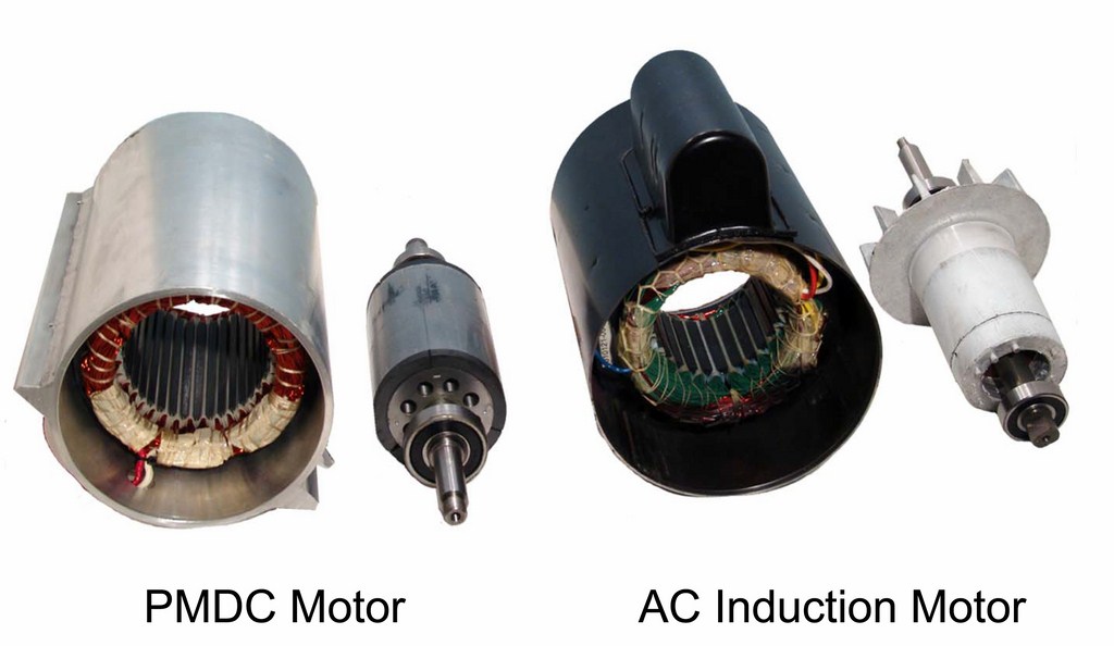
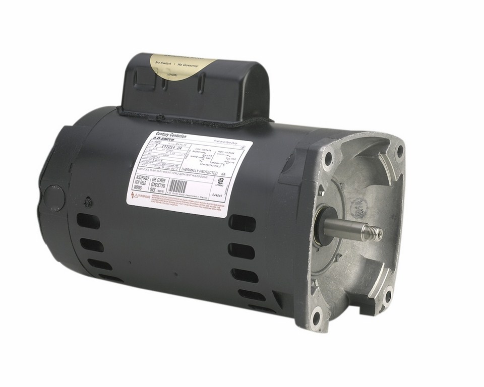
| Figure 3: Internal views of a PMDC motor (at left) and an AC induction motor (at right). |
Three-phase AC motors typically feature high power factors and efficiency, but they require a magnetizing current. By contrast, a permanent-magnet DC (PMDC) motor does not require that current, so it offers higher efficiency and power factors over a wide range of motor-shaft rotation rates (Figure 3). Moreover, PMDC motors are also available with totally enclosed, fan-cooled (TEFC) technology, which adds to motor life by managing heat and sealing the motor against moisture.
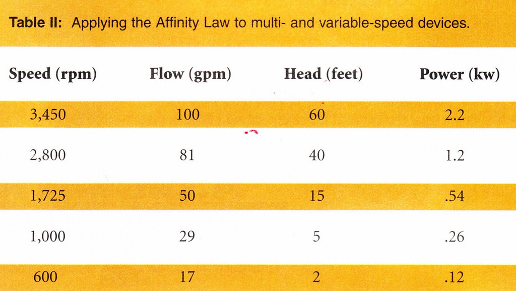
In either case, the drives allow for adjustment of the rotation rate of the motor between one and 3,450 rpm (with 400 rpm constituting the functional low end for most applications). This offers advantages in your ability to make custom adjustments to flow and lowers energy consumption by allowing motors to run in lower shaft-rpm ranges – big news when it comes to working effectively with the Affinity Law (Table II).
Indeed, when these motors are used in conjunction with properly designed hydraulic systems in appropriate applications, the cost savings can be dramatic. Those benefits come with a downside, however, in the higher initial cost of the pump and controller and the added cost of the larger plumbing required by the oversized drive.
[ ] Load-Sensing Motors: This is the newest technology to reach the marketplace. Although still relatively unproven, load-sensing motors do two things: They either correct flow or can be used as suction-vacuum release systems (SVRS).
Flow correction occurs when the pump holds a fixed flow rate as the system curve changes. By contrast, an SVRS has the sole purpose of preventing suction entrapment by sensing dramatic changes in vacuum level and shutting off the system in response. By law, all SVRS units must comply with the ANSI/ASME A1.12 19.17 standards – an important point to ascertain before applying one of these systems.
Although their manufacturers have been vocal about the risks of suction entrapment and see their products as the only solution to the problem, there are many in the industry who counter that the combined use of proper flow rates, split main drains and anti-vortex drain covers is a more reliable approach.
APPLIED TECHNOLOGY
Before we move on to the next article in this series and cover the specifics of motor and pump selection, let me end this one by amplifying a key point: When approaching the choice of motors and pumps, it’s important to consider not only the constraints of line velocity and the equipment you need to drive water at the desired rate, but also the basic compatibility of the components at hand.
This is a factor to which we’ll return time and time again as this sequence of articles unfolds in the year to come. In that context, selecting appropriate motor/pump technology will become a relatively simple process for a wide range of hydraulic systems including (with swimming pools and spas, for example) the primary filtration array, a spa’s booster system, an automatic or in-floor pool cleaner, a solar heater and various water-in-transit effects including vanishing edges and perimeter overflows.
At the same time, it’s important to note that there are no automatic or blanket choices here: No single motor type will be the right choice for all applications, so as you move into the selection stage, you need to be aware that your choices should be driven less by habit or familiarity than by the specifics of the hydraulic applications and the economics of the tasks at hand.
It takes some insight, but once you know which factors to weigh, it all becomes clearer.
Steve Gutai is Director of New Product Development, Hydraulics and Heating Systems, at Zodiac Pool Systems, Vista, Calif. He may be reached at steve.gutai@zodiac.com.