


Detail S129: Coffer Coordination

Creating containment vessels, i.e. coffers, on hillside pools often requires building the coffer far head of the pool itself. As Richard C. Kremer points out in this latest Beneath the Surface detail, doing so requires careful design coordination with general contractors before the coffer is built, as illustrated by this clever containment solution.
By Richard C. Kremer
Oftentimes, we’re brought into the design process late in the game. This means adjusting to design and engineering decisions that have already been made and frequently cannot be changed. The coordination required can be complicated for above-grade pools.
In places like Los Angeles County where there are numerous hillside pools, building departments have become increasingly concerned with preventing any water from escaping the pool shell. We’re always concerned with creating watertight structures, meaning we’ll employ enhanced specifications for steel and leak prevention measures, along with specs for concrete strength.
In these situations where even a small leak can spell disaster, we’re asked to add another layer of prevention in the form of a coffer, basically a concrete containment vessel that surrounds the pool.
It’s a relatively simple concept, but it does often require careful coordination with general contractors and other project team members. If we don’t get ahead of the situation there a real possibility that we’ll run out of physical space.
The first thing we need to know is what’s the edge treatment. If, for example, there’s an edge overflow of some type, we could be faced with a situation where there is no room for any kind of a gutter. That means you either would have to go with a traditional coping edge, or you’d need to reduce the pool’s interior dimensions, which might not please the owner.
In this case, the pool had a great view of the ocean meaning it was very likely to have a vanishing edge. We first had to determine if that was the case, and then work with the structural engineer to design the coffer to allow for the edge. By recessing the coffer into the pool structure, we avoid having a visible expansion joint around the three dry edges.
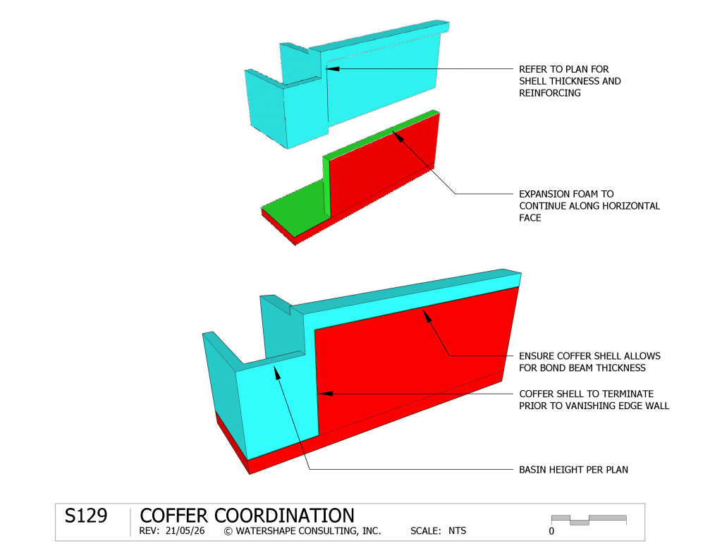
In this example we interfaced the coffer wall with the pool shell so that the edge wall doesn’t have to cover both the pool shell and coffer walls. We engineered a three-sided coffer that terminates prior to the vanishing edge wall, while acting as a base beneath the entire pool and catch basin. Had we not been involved early in the process; we could have been confronted with a coffer that would have compromised the vanishing edge wall and catch basin.
In this case, we also had the equipment located beneath the pool, which made it all the more important that no water escaped beneath the pool. We included a drainage mat beneath the coffer so that any ground water present would drain to daylight.
Note: In this drawing, the pool structure is in blue and the coffer is in red. The green strip is expansion material that will allow for a small amount of differential movement between the two structures.
Richard C. Kremer is project design manager for Watershape Consulting in Solana Beach, Calif. He joined the firm in 2009, overseeing coordination and detail for architectural, mechanical, structural and landscape design.