


Shocking Truths


In the spring of 1941, my mom and dad, my sister and I moved into our brand-new house on Ardmore Avenue in one of northwest Detroit’s real estate developments. It was a thoroughly modern house, with all of the latest high-tech features – the garage door moved upward to open, instead of swinging left and right like barn doors, and the furnace in the basement was operated by natural gas, eliminating forever the need to shovel coal. The house cost $5,550.
From an electrical standpoint, the house was up to the codes and standards of its day – albeit a far cry from what is required today. The wiring was a two-wire system with no ground. All of the receptacles had two equal-size slots, and that was just fine because anything we wished to plug into these receptacles had a two-pronged plug at the end of its cord.
A fuse panel in a bedroom closet contained four 15-amp fuses. That was it: four fuses to protect the entire house. When considered from today’s viewpoint, it sounds totally inadequate. In retrospect, however, I must admit that our family, as most in that era, probably didn’t own enough electric appliances to overload those fused circuits, even if we had plugged everything in at the same time.
SAFETY FACTORS
The primary goal of those four fuses was to prevent fires due to overloaded wiring. That’s a legitimate concern: Any time a defective appliance causes too much current to flow, the wiring in the walls of the house can become hot enough to start a fire. Or, if there’s a breakdown in the insulation of the house wiring, a heat-producing short-circuit can start a fire. In either case, the fuse on the associated circuit will blow and stop the flow of electricity.
“Melt” might be a better word than “blow,” as is indicated by the Latin root for the word fuse – that is, fusus, meaning “to melt or pour.” That is actually what takes place within the fuse: All of the electric current running through a fuse passes through a short link of metal that has a relatively low melting point.
The fuse manufacturer uses links of various melting points and different thickness to create fuses that will melt at different amperage levels. If the amount of current flowing through the fuse exceeds the fuse’s amp rating for a predetermined length of time, the fusible link will melt, stopping the flow of electricity.
Unfortunately, a fuse is a one-time device. Once the fusible link has melted, the fuse must be replaced – a substantial drawback, because if you don’t have a spare close at hand, you’re going to be left in the dark. Horror stories abound about quick-fix schemes to repair a blown fuse.
Putting a penny in the fuse socket and screwing the blown fuse on top of it to hold it in place is a favorite. I don’t know if anyone has ever calculated the current-carrying capacity of a penny, but my guess would be more than 100 amperes. Frightening.
The shortcomings of fuses were overcome by the development of relatively inexpensive circuit breakers. The most common type of circuit breakers still rely upon the heat generated by the current flowing through them to do their jobs, but in a significantly different manner than a fuse.
The heart of a thermal circuit breaker is an item called a bimetallic strip. It is a lamination of two different metals that causes it to bend a predetermined amount depending upon temperature. The electric current passing through the circuit breaker heats the strip as it flows through it, causing the strip to bend in relation to the amount of current flowing.
When the flow of current exceeds the rating of the circuit breaker, the strip will bend far enough to release a latching mechanism that allows powerful springs to force the current-carrying contacts to open, thus “breaking the circuit.” After the circuit breaker has cooled down a bit, moving its operating handle from OFF to ON will close the contacts and reset the latching mechanism. (You can feel the tension of the springs when you reset the breaker. It’s much liking cocking a gun.)
PERSONAL PROTECTION
While there is no doubt that the circuit breaker’s ability to be reset makes it a far more desirable product to live with than throw-away fuses, it must be remembered that their primary missions are the same – to prevent fires in a building’s wiring and in any appliances connected to them. Neither of these devices provides any protection against electric shock to people.
The problem with people and all things electric is simply a matter of dosage. We people can take electricity only in very, very small doses. We surround ourselves with appliances and devices requiring many amperes to operate, yet when we talk about the human being and electricity, we must talk in miniscule fractions of an ampere. In fact, we must deal in thousandths of an ampere to be on the safe side.
Several tables have been published through the years showing the effects of various amounts of electric current passing through the human body. A sampling: For men, a tingling sensation starts at 0.0011 amps; for women, it starts at 0.0007 amps. For men, a painful shock from which they can still let go begins at 0.009 amps; for women, that’s 0.006 amps. For men, a severe, painful shock from which they can’t let go and which causes breathing to stop starts at 0.023 amps; for women, it commences at 0.015 amps.
(I have often wondered where in the world they find the volunteers for these studies. What possible inducement could there be that would entice someone to have their breathing stopped?)
There’s general agreement that an average, healthy adult will survive a short-duration electric shock not exceeding 0.006 amps. He or she certainly will know what’s happened, but it’s possible to walk away from this level of exposure with no lasting trauma.
Now think back to the 20-ampere fuse or circuit breaker protecting the wiring in a house: That’s over three thousand times the amperage required to hurt the human being!
Fortunately, we now have a device whose primary mission is to protect people from electric shock: the ground-fault circuit interrupter (GFCI). That name requires a bit of explanation: a “ground-fault” exists any time the electrons flowing in a hot conductor find a path to earth/ground. That path is called a “circuit,” thus “ground-fault circuit.” This device will sense the existence of a ground fault circuit and “interrupt” (or open) the circuit to stop the flow of current.
Generally, it takes two failures in a product to set the stage for a ground fault that may be hazardous to people: an electrically hot conductor inside the product must be touching the metal housing of the product, and the grounding conductor normally connected to that metal housing must be broken or missing – or its connector is so loose that the grounding connection is no longer adequate.
IN THE FIELD
These potentially life-threatening failures can be brought about by a defective installation, negligent repair techniques, abuse of the product – or reasonable wear and tear, in the case of the internal circuit conductors.
Let’s take a look at what happens when a failure occurs (Figure 1 below). Here we see a person getting a mild shock from a defective pump. The ground-fault circuit starts where the person’s hand is touching the pump and continues through his body to his foot, which is in contact with earth/ground.
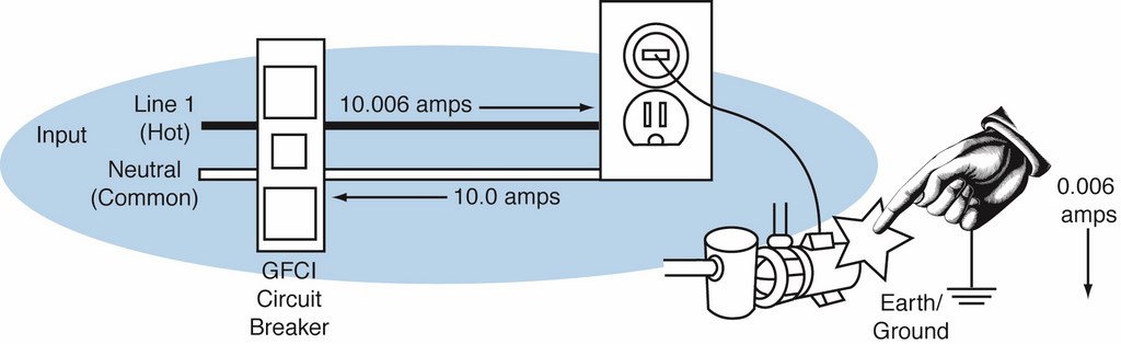
| Figure 1: A pump defective grounding connection and an internal short circuit to its metal motor housing. |
The numbers in the figure indicate that the pump is drawing 10.0 amps. The laws of physics tell us that if there are 10.0 amps of current flowing into the pump motor, then there must be 10.0 amps flowing back to the source at any given instant in time. Because of the ground fault, however, we see that 0.006 amps are flowing through the person to earth ground, so we have a situation where 10.006 amps are flowing into the motor, and only 10.0 are flowing back to the source.
It is the job of the GFCI to monitor the amount of current flowing from the source to the appliance and back to the source, and to interrupt the flow of current any time an imbalance is detected that exceeds 0.006 amperes.
Now let’s look at a typical GFCI (Figure 2). Note that the Line 1 conductor and the neutral conductor both pass through the hole in the donut-shaped differential transformer. Any time an electric current flows through a conductor, a magnetic field is generated around that conductor.
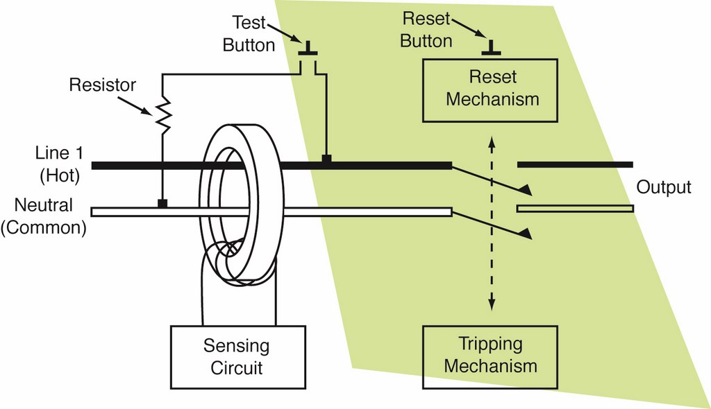
| Figure 2: A 120-volt GFCI, shown tripped. |
That magnetic field would be sensed by the transformer, and a voltage would be generated that would be sent to the sensing circuit. But because both the Line 1 and neutral conductors are passing through the transformer together and their normal voltages are exactly the same, the two magnetic fields cancel each other out and no voltage is generated to be sent to the sensing circuit.
In a ground fault condition such as that depicted in Figure 1 on page 66, the Line 1 and neutral voltages will not be exactly the same: They will differ one from the other by the 0.006 amps of ground-fault current flowing through our person. The two magnetic fields will not cancel each other out, and a small voltage will be generated by the transformer and sent to the sensing circuit.
There the voltage is amplified and sent to the electromagnet in the tripping mechanism. The energized magnet pulls in a latch that allows spring pressure to open the contacts in both lines, shutting off all current flow. All this happens in less than 0.05 seconds.
All GFCIs are equipped with a test circuit to allow the user to be assured that the unit will work properly when needed. When the test button is pushed, it causes a small amount of current to flow through the transformer on one conductor only, thus simulating an imbalance such as would be caused during a ground-fault condition. It is a good practice to test GFCIs frequently.
For some years now the combination GFCI/circuit breaker has been available. These devices replace regular circuit breakers in panel boards and sub-panels, providing us with the best features of each unit in one convenient package.
In a future article, I will address specific uses of GFCIs as required by the National Electrical Code – with an emphasis on their use around watershapes of all types.
Jim McNicol was a technical consultant to the swimming pool, jetted bath and spa industries. He worked on development of equipment standards for pools and spas throughout his career and was honored for his service by the National Spa & Pool Institute.