


A New Dimension

There are some things that are better seen than described.
In the case of pool and spa equipment, for example, there are situations in which manufacturer instructions or two-dimensional plan drawings simply do not give the installer all the information needed to get things right the first time. As a result – and as everyone who installs equipment sets knows – the plumbing and layout of the equipment usually requires some level of on-site improvisation.
In our work of designing hydraulic systems for complex watershapes – everything from commercial pool facilities to interactive waterfeatures and fountains – we’ve seen the need to find a way to specify precisely how we want our equipment sets to be installed. No two-dimensional plumbing schematic or manufacturer-supplied manual does that part of the job. That is, they do not completely delineate the way combinations of components should all go together.
The shortcomings in this documentation have to do with the fact that the illustrations don’t show equipment arrays in three dimensions, despite the fact that pumps, filters, heaters, chemical systems, control systems and everything else that collides on equipment pads is plumbed in three dimensions. This is why plumbers so often have to improvise.
This is also why, to address that gap, we began developing representations of equipment sets that give information that simply can’t be communicated with flat, two-dimensional renderings.
REASONABLE MEASURES
We headed in this direction for two main reasons: First, we wanted to provide tight specifications that defined tasks at hand down to the finest level possible. Second, we wanted our systems to be plumbed a certain way. Without firm guidance, there was simply no way to ensure that what we designed would be installed as specified.
What we’d been running into was the fact that, with the advent of new technology, plumbers were often asked to install pieces of equipment they’d never seen before. In an ideal world, the installer encountering an unknown device would sit down and read through all of the installation instructions to make certain he or she understood critical installation factors – but that’s simply not the reality of the process.
Occasionally, of course, things are done the right way and instructions will actually be followed, but nine times out of ten, that’s just not the case. Given a situation in which we don’t know how much the installers will be willing to read of if the project is even happening in an English-speaking country, we decided that we were leaving too much to chance in critical, functionally significant areas of our projects.


| No matter how clean the two-dimensional illustrations we generated for our equipment sets were, they never gave plumbers and installers all the information they needed to follow through on the job site in a direct, sensible way. When we added a third dimension, however, spatial relationships were dramatically clarified – and the layout and installation processes became radically simplified. |
In our observation, most watershapers simply make the assumption that the equipment installation will be handled competently, but these days, and given the increasingly critical operations of modern watershapes, we see that a hands-off approach simply leaves too many issues to chance – an unacceptable state of affairs.
For us, the question became: How are we going to communicate with our plumbers? Assuming the worst – that is, that they do not read the information available to them – the solution seemed obvious: What we really needed to do was to make the documentation for plumbing installations pictorial.
Our thinking was, if the installers were looking at a three-dimensional image, it was far more likely they would be able to visualize exactly what they needed to do. After all, these images tell the whole story – of how the valves are oriented, for example, and the way the fittings go together or the manifold should look when it’s finished.
In short, such a pictorial rendering would show them the proper orientations of all the major pieces of equipment in one neat, entirely visual package.
SPACE SAVERS
As we considered these possibilities, it also occurred to us that three-dimensional plans might help us out in a number of additional ways. The space required for equipment is, for instance, a major issue that three-dimensional renderings helped us resolve.
In many situations, architects, landscape architects, general contractors or developers will assign “space” for an equipment pad without knowing the size of the actual set. As best we can tell, these spaces are typically allocated as a matter of guesswork based on past jobs or, perhaps, projects seen elsewhere.
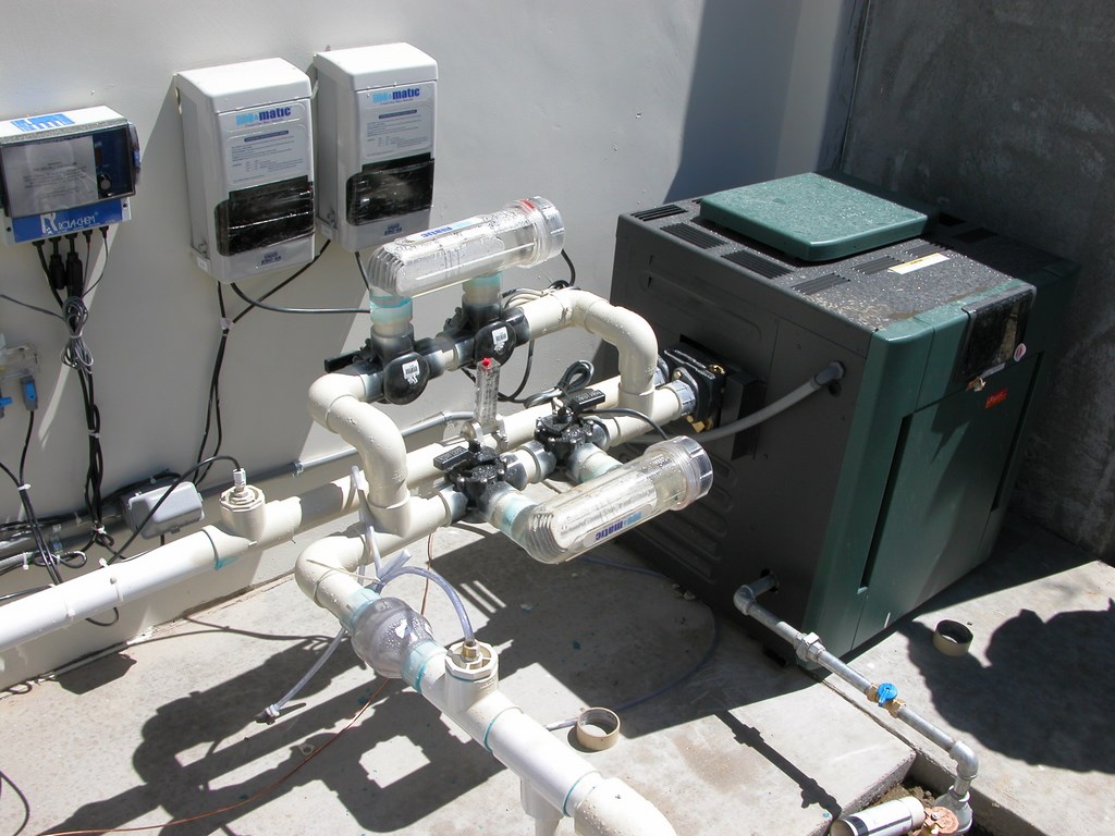
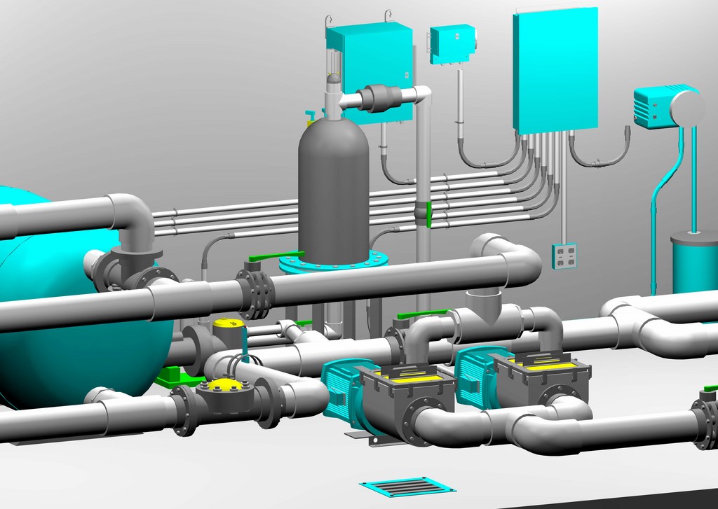
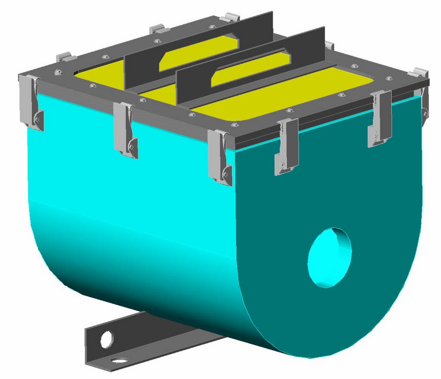
| The improper installation of one of these salt-chlorination cells is what led us to get involved in detailing our equipment sets in three dimensions. (Notice that one cell is installed in the correct upright position and that the other is at about a 90-degree angle, despite the supplier’s recommendation.) Working in three dimensions, we were able, without taking up any additional space, to illustrate a better way to get the job done and allow both cells to produce the same level of chlorine. |
It’s no secret that many of these designers want lots of functionality in their watershapes but really haven’t a clue what type of equipment is involved in making it happen, let alone its size or physical orientation of that equipment relative to other devices on the equipment pad. In two-dimensional drafting, we can show a great deal of detail related to basic equipment dimensions, pipe sizes and component connections, but experience shows that these flat plans are inadequate as on-site guides.
By contrast, three-dimensional views bring us much closer to the way things actually look and go together in the field. This clarity enables specifiers to nail down actual space requirements with great precision, thus avoiding the need for changes on site where space comes at a premium – especially if the equipment is to be installed inside some kind of building or structure. When things go wrong, options such as moving walls or changing the way the system works because of unalterable space limitations are far from desirable.
With three-dimensional views, objects have the same “volume” they have in the real world, so we’re able to plan the space for maximum efficiency and with great confidence in the space solutions we develop. We know for certain, for example, if we’ll have enough straight piping to install a flow meter. And if we have two pieces of parallel plumbing and one is to include a check valve, we can see how close together they are and make allowances for the fittings – details that make a huge difference in the field and that can become problems when plumbers improvise.
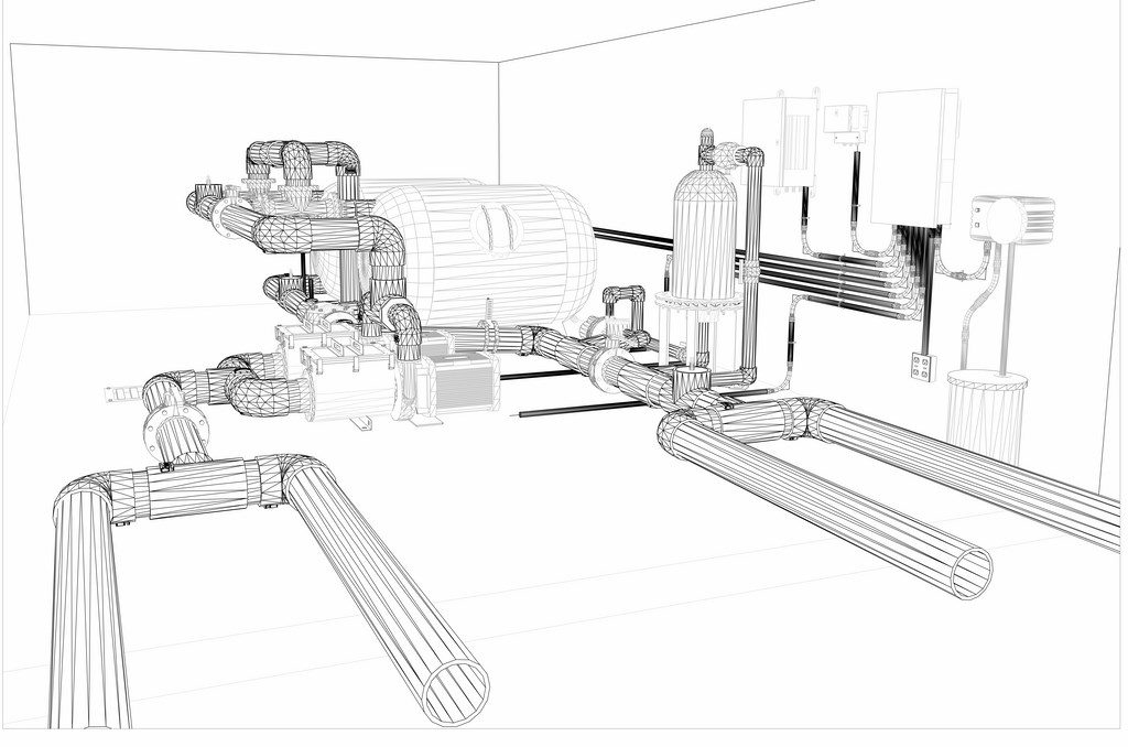
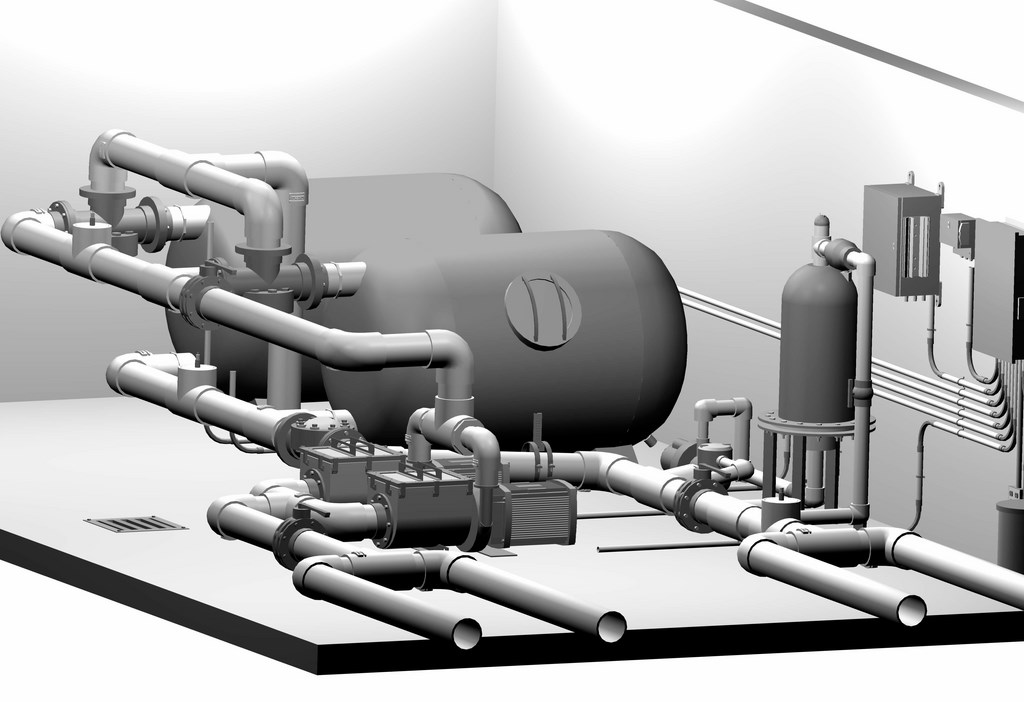
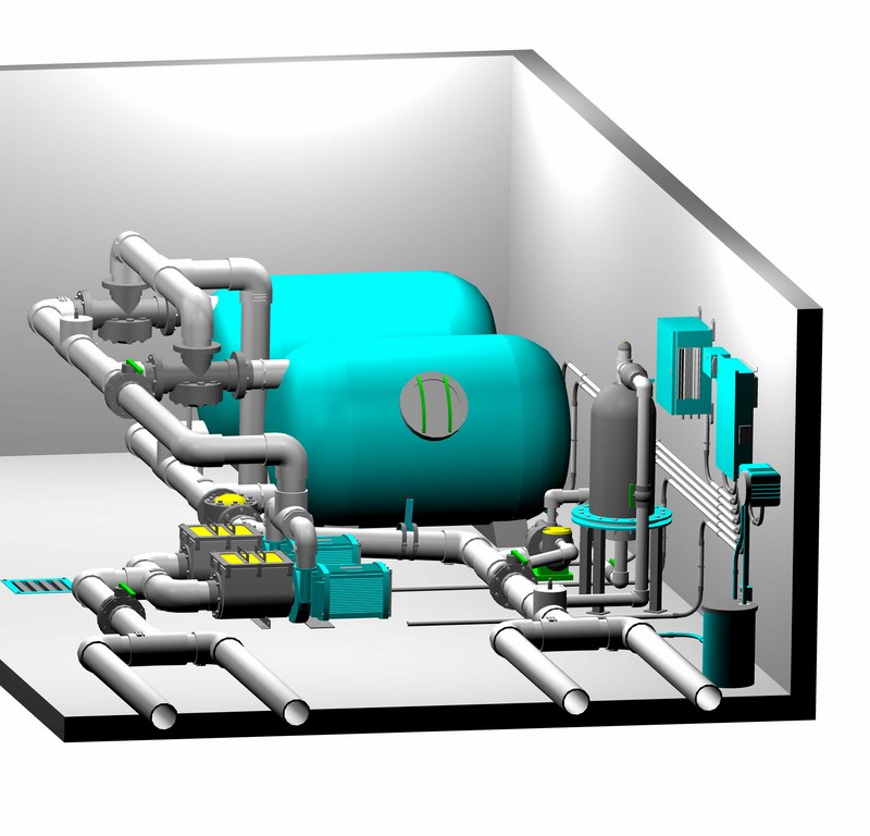

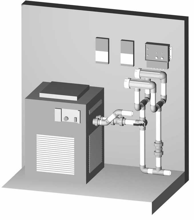
| The world of three-dimensional drafting starts with the assembly of wire-frame models (left) that are subsequently surface-rendered to produce final textures (middle left) and colors (middle right). Once this information is captured, we can make alterations in networks without having to start from scratch. Moreover, because we can see how everything fits in dimensional terms, we can make the equipment set as compact as possible while still maintaining a focus on serviceability. Best of all, we can generate drawings from different perspectives (right), moving around the set to give complete, detailed guidance to plumbers and installers – and in this case noticing an issue with routing of the return lines that we resolved before anyone else saw the drawings. |
Or consider ports on heaters, which are typically very close together: If they’re plumbed with straight pipes only, no problem, but as soon as you add a check valve or some sort of directional valve, things get far more complicated. We’ve spotted issues in our three-dimensional drawings – such as the arm of a valve not having adequate room for complete rotation – and have been able to address them at the schematic stage rather than on site. The adjustments may only involve fractions of inches, but in terms of basic functionality, they can be extraordinarily important.
When we started down this path, our method involved creating two-dimensional schematics first – still a necessary step for health and building inspectors. What we found, however, is that we were changing so many details in the two-dimensional plans as a result of what we were seeing in the three-dimensional renderings that we now prepare our three-dimensional schematics first – then work back to the flat plans for the inspectors.
FLESHED OUT
Developing three-dimensional images for equipment arrays is nothing new in other industries, but as far as we can tell, it hasn’t found wide application in the pool and spa realm.
The process is straightforward: We render the images in a CAD program that’s used for exactly this type of application across a wide range of design disciplines. But where those who design everything from automobiles to landscapes can refer to web sites loaded with stock images they can use, we’ve had to go to great lengths in obtaining the accurate dimensional data required to generate the glossary of images we’re using.
| Even small, residential waterfeatures can benefit when we illustrate their equipment pads in three dimensions, basically because we leave nothing to the imagination so there’s no guesswork at installation time (left). So far, few manufacturers are ready to supply us with three-dimensional images, so we generate our own using their two-dimensional drawings and plug them into our set drawings when needed, as with this strainer (right). It can be a time-consuming process, but we see it as being well worth the investment. |
In many cases, we’ve gone to manufacturers to obtain original design drawings they used to make their various pieces of equipment. In others, we’ve been able to find what we need in product specifications. The basic point is that we had to go well beyond the kind of information found in a typical catalogue or brochure.
We need two key pieces of information to generate our images: correct dimensional information on the object itself as well as exact locations of the inlets and outlets for plumbing and electrical connections. Everything else in the image is incidental or cosmetic and makes no difference so long as the key dimensions are correct. Just the same, we try to pin the volume and shape of the objects as close to reality as possible as a visualization tool.
|
Salty Solutions As watershapers and designers of hydraulic systems, we are expected to be up to date with all of the newest products available on the market. Among new devices gaining a strong foothold in the marketplace, salt chlorination units are among the hottest – but they come in such an array of configurations and with such a wide variety of installations specifications that it’s difficult for installers to keep up. We’ve run into lots of issues with the plumbers who install salt cells and their housings every which way, even when presented with detailed instruction manuals. Their willingness to improvise frequently leads to incorrect installations and poor performance, and it’s a plain fact that our former two-dimensional mechanical plans weren’t of much help in conveying the intricacies of the installations. We’ve corrected the situation with three-dimensional details that show plumbers exactly how to arrange things and avoid the conflicts that arise when certain cells are, for example, set too close to heaters. (This conflict changed our standard detail and caught the attention of the device manufacturer’s technical representatives, who had never contemplated the complexities of working around a heater header.) The illustration shown here indicates the way the pipe had to be bowed in this case to allow the connection of the cell – a case in which a three-dimensional rendering cleaned up a potential problem and is helping the manufacturer eliminate heater problems with future projects. — M.H. & D.B. |
Accuracy is most critical with new products installers haven’t seen before (such as the saltwater chlorinating systems mentioned in the sidebar at right). It’s also unusually important with electrical conduit and control boxes, especially given the fact that more and more equipment can be tied to control systems these days. If we’re able to show conduit layouts exactly, installation will go faster, will look neater and will seem more “professional” because the installers know how everything should look.
The level of detail is indeed fantastic. We can clearly define routes for chemical-injector tubing, for example, that prevent problems of pinching or crimping that can arise when installers improvise in the field. With our drawings, we show the installer that the tubes run through their own conduits, effectively creating double containment that will prevent damage and ensure proper operation.
Of course, all of this can be spelled out in a specification or represented in two-dimensional drawings, but showing it in three dimensions enables us to illustrate exactly where and how the tubing and conduit should run relative to everything else on the pad. As a result, the odds in favor of proper installation increase dramatically.
TIGHTER BIDS
Another benefit to this type of drafting is that it enables contractors to develop extremely accurate bids. If so inclined, you can measure the required plumbing to the fraction of an inch and make spot-on counts for fittings and other important components.
In most cases even these days, bidding on construction of equipment pads involves a great deal of guesswork and inclusion of fudge factors that cover items that can’t easily be measured or counted without the sort of detailed rendering we’re pursuing. We don’t like guesswork in our projects, and this system effectively eliminates it.

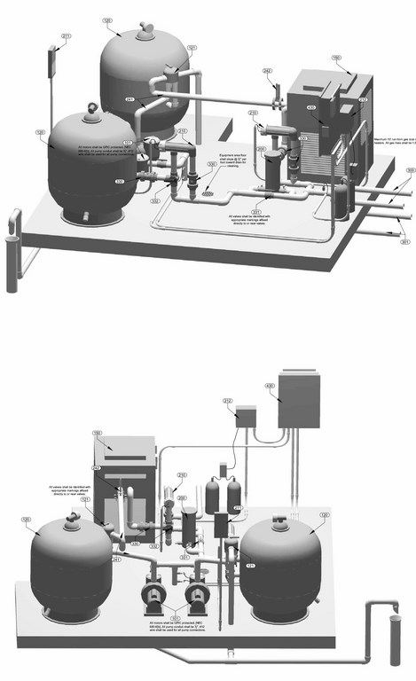
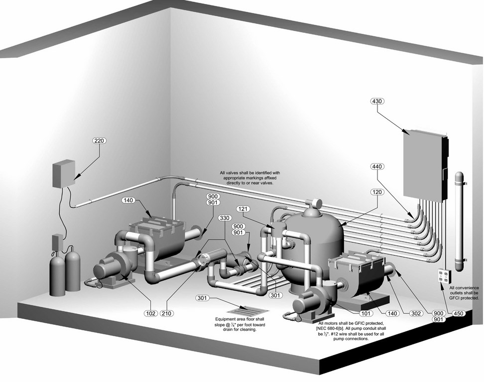
| A key advantage of the three-dimensional approach is the ability it gives us to rotate the image on screen and generate drawings of every key angle a plumber or installer might need to consider. This ability to see interactions between products and piping was never possible before – except on site, by which time the undesirable improvisations had usually begun. Now we can virtually fly into a set of equipment, navigate around potential issues and make certain what we’re after is completely buildable – first time, every time. |
Finally, because we can ensure proper installation of system components, the reliability of those pieces of equipment increases substantially. We’re not spending much time in troubleshooting at start-up as a result, and the frequency of replacement or warranty work has dropped dramatically because almost everything is being installed as specified for optimal efficiency.
When problems arise, we often spot the trouble simply by comparing the actual pad to the three-dimensional rendering, greatly diminishing the need for time-consuming detective work. To be sure, this approach has required an investment in the technology and in developing a roster of images. But already, the benefits to our business have far outdistanced the expense and hassle of getting up to speed with this type of drafting.
We see this as an evolutionary “next step” for the watershaping trades – one that stands to benefit everyone from equipment suppliers and designers straight through to installers and end users. It’s an approach that seriously reduces frustration at every level and dramatically increases the possibility that equipment will be installed properly the first time around.
It’s a positive development for all project participants – and another operational function we no longer leave to chance.
Mark Holden is a landscape architect, pool contractor and teacher who owns and operates Holdenwater, a design/build/consulting firm based in Fullerton, Calif., and is founder of Artistic Resources & Training, a school for watershape designers and builders. Holden and Donovan Brown are principals at Holdenwater, a design firm based in Fullerton, Calif., that offers design and engineering services to landscape architects and pool builders working on elaborate watershapes including swimming pools and spas, community aquatic facilities, fountains and waterparks. The partnership’s goal is to work to the highest standard possible in all aspects of watershaping. Holden can be contacted at [email protected].