


Over the Edge

From the grandest waterfall to the smallest courtyard fountain, water flowing over an edge is one of the most compelling of all watershaping “looks.” Whether it’s a vanishing edge or a slot overflow or a trough, runnel or waterfall, these effects all use one common concept – that is, the weir.
Simply defined, a weir is a barrier or dam placed in a channel behind which fluid backs up and then falls through a notch and down the face of the weir. In most watershaping applications, water travels over the weir’s edge or brink and into some kind of lower basin, trough or pool.
Physically and visually, these systems are driven by gravity and water flow. Once the water rises to a critical level above the weir’s edge, gravity takes over and atmospheric pressure forces the water down the face of the weir, creating a low-pressure area between the lower surface and the downstream face of the weir wall.
(This low-pressure area is the reason that water tends to stick to the face of the weir wall. As we will see further in our discussion, extending the surface of the weir beyond the dam wall or designing with end contractions can help reduce this problem.)
Determining proper weir flow rates can be a challenge, but following a few simple steps – that is, determining proper weir design; calculating the required flow rate to achieve the desired affect; and establishing a circulation system that operates with the required flow rate – can take you a long way toward ensuring success in your designs.
As one might expect, there are complex formulas and mathematical processes that can be used to pinpoint the right details. Well beyond any such exercise, however, the nature of weirs requires an understanding on the part of the designer or builder of how they work and how they can be used to generate desired effects.
ON THE SURFACE
For all the hydraulic science that can go into setting up a weir, it’s clear that the main reason they are used in watershaping projects has to do with aesthetics. For that reason, I’ve noticed a tendency among designers and builders to approach weir design with casual, ballpark calculations of required flows and, later on, rely heavily on valves and upsized pumps to mask inefficiencies in (or the absence of) hydraulic design.
Such approaches come up short, and I would argue that these systems should always be designed to come as close as possible to a defined, targeted flow.
|
Gravity of the Situation Weirs are very different from other common features that create visible flows of water: Where jumping jets and fountain sprays are driven by pumps, weirs rely mainly on atmospheric pressure and the force of gravity to get their aesthetic work done. Yes, a pump raises the surface of the water over the edge of a weir, but it is gravity that causes the water to flow over the edge from one level down to another. In hydraulic systems, the head or resistance a pump must overcome to make water flow is a huge factor. In a weir, however, that head only exists up to the point where water crests over the edge: From that point on, gravity is the only operating factor. — S.G. |
Consider a typical vanishing-edge pool: Such a system requires separate pumps to drive the circulation system and the edge effect, an engineered catch basin and a weir over which the water flows to create the effect. Without care in system design, it’s likely you will overbuild the system (at considerable extra expense) to achieve sufficient flow over the edge, or that you will undersize either the plumbing or the catch basin and produce a system that performs poorly. If things go wrong here, the result might be flooding or some other form of property damage.
Why would you want to send too much water over a vanishing edge, thus requiring construction of a larger-than-necessary catch basin? Why would you create too much flow in a slot-overflow system, necessitating use of an upsized surge tank? Simply answered, it’s always better to design these systems so that proper flows are maintained and associated structures are properly sized.
Thus, to achieve the effects our clients crave without the problems and inefficiencies that plague over- or undersized systems, anyone working on weir-based watershapes must have a clear understanding of the principles involved. And this applies across the board with everything from vanishing edges to naturalistic waterfalls: Although they look different and achieve distinctly different visual effects, the basic design ideas are all the same.
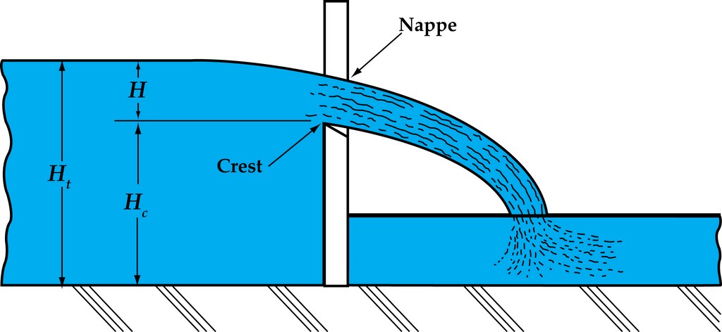
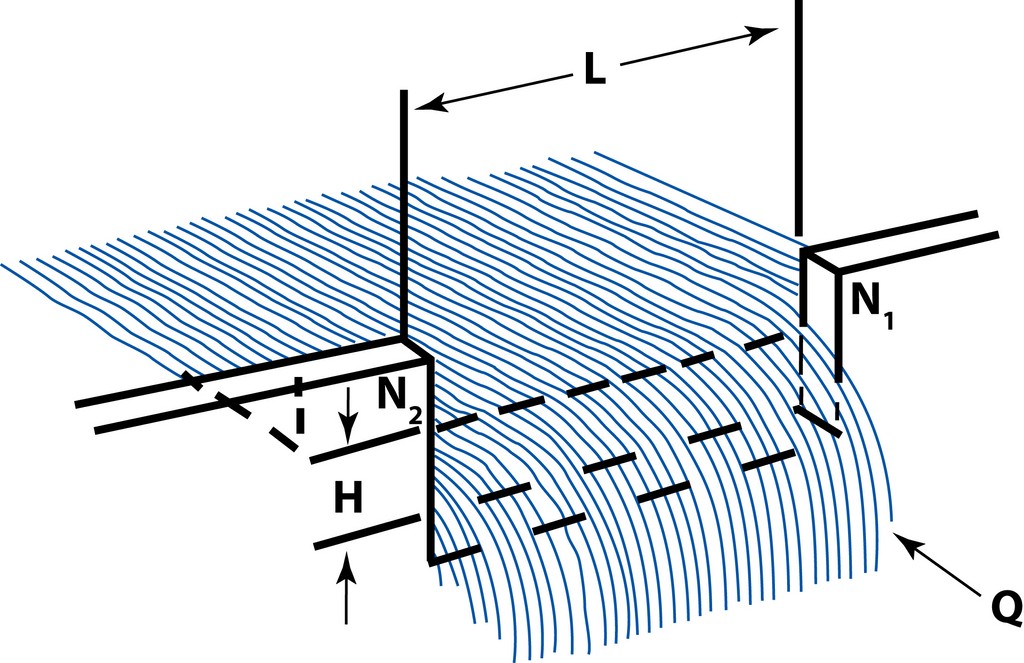
| Figure 1: An illustration of nappe and crest – key terms used in measuring the flow of water through the notch of a weir. (Drawings by Bridget Ross, Jandy Pool Products, Petaluma, Calif.) |
The water or fluid that falls through the notch of a weir can be measured in terms of head. The height or head of the water moving downstream over the weir is called its nappe – that is, the thickness of the water that can be measured (typically in inches) from the top of the weir crest to the surface of the water (Figure 1).
The discharge over a weir depends on three factors: the dimension of the notch (its shape and length), head of the fluid (based on the difference between the head at the crest and at the surface of the liquid), and the approaching velocity of the water as it enters the weir. Knowing precisely what’s happening at this place – and anticipating what will happen visually once the water breaks the plane – enables a watershaper not only to control aesthetics, but also to enhance efficiency.
CONSIDERING CONTRACTIONS
Before we go on, let’s run through some of the terminology hydraulic engineers use in discussing weirs. There’s a distinct possibility these terms will never be of use to you in discussing projects with clients, subcontractors or anyone else involved in your projects, but I find it useful to look at things the way the engineers do as a means of understanding what they consider to be important.
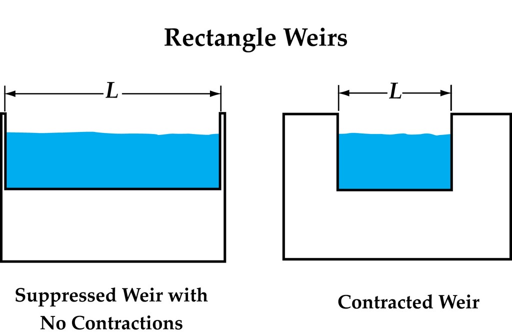
| Figure 2: Of all weir types, rectangle weirs are those most commonly used in watershape applications. |
In their world, rectangular weirs (the most common sort) fall into two basic categories, the first known as suppressed weirs, meaning they have no end contractions enclosing them at their sides – the most familiar example in our work being perimeter-overflow systems (Figure 2). By contrast, non-suppressed weirs have contractions, with vanishing edges, troughs and runnels falling into this category.
All weirs add to head in varying degrees. Weirs with end contractions often generate more resistance than do those without contractions – small differences, perhaps, but significant nonetheless because they are related to the head (or resistance) that a given system includes. The number of contractions is sometimes factored into weir formulas: If a watershape is designed with many runnels, for example, each have two contractions and all must be accounted for in a weir formula.
Weirs that have contractions – that is, weirs that are less than the full width of the channel or runnel – provide a considerable amount of head. In a vanishing-edge system, in which a long weir is bracketed at either end by barriers of some sort, the contradiction contributes relatively little head relative to the length of the weir.
Contractions of any sort or degree come into play in a practical sense in that they accelerate the flow rate by narrowing the notch or channel through which the water flows. In that sense, their performance resembles plumbing in which, given a constant amount of pressure or vacuum, water will flow faster through a smaller pipe and more slowly through a bigger one.
In the case of a vanishing edge or slot-overflow pool, that acceleration of flow is miniscule because the contractions are so minor compared to the overall width of the weir. In a narrow runnel, however, the contractions dramatically increase the rate at which water falls over an edge.
In generating visual effects, you can assume that if you want the flow to be fast and vigorous, what you need to do is narrow the channel. If, by contrast, you want to slow the water down, you need to widen the channel. That’s a very different way of thinking about or manipulating flow than is simply relying on an upsized pump – which is what too many people do regardless of the physical characteristics of the weir they’re using.
ON THE BRINK
The first step in designing these systems in a formal way involves establishing the flow required over the edge of the weir. Remember the steps: Choose a flow rate that will work for your design, calculate that flow rate, and finally, design a system to accommodate it.
To be sure, we could use mathematic coefficients to express these steps, but it’s easy enough to grasp the issues on an intuitive level: We know that water flowing over a rough surface (an exposed aggregate finish or stone) will inherently provide more head than will a smooth surface (tile or glass). Nonetheless, those differences are relatively minor in all but the most extreme cases, so digging deeper isn’t usually necessary as part of system design.
What’s more relevant is the profile of the weir edge. A vanishing-edge dam wall that’s pitched back toward the pool, for example, provides more surface over which the water must flow across the length of the weir. By contrast, an edge battered away from the pool provides much less resistance to flow.
Ultimately, it’s all about resistance and learning to work with and manipulate it. With a vanishing edge or perimeter overflow, for example, your aim is to create a precise, sharp edge that holds back as much water as possible right up to the point where it crests over the weir’s edge. In a runnel or waterfall, you’re goal is exactly the opposite: You want to create as little resistance behind the weir as possible.
In other words, the physical design of the weir has as much to do with generating the visual effect as does the flow rate over the edge. You can make water appear to have a very high flow rate just by configuring and orienting materials at the edge: A quarter inch of water flowing over a knife edge is going to look quite different from that same quarter inch flowing from the end of a runnel or notch, as in the spillover from a raised spa.
If you approach this as a science, the dynamics of weir design are quite complicated – as proved by the fact that engineers spend their entire careers learning about their subject. From a practical standpoint, you can achieve desired effects in the relatively simple realm of watershaping by keeping a few basics in mind.
The point here is, no matter what type of weir you’re working with and no matter what sort of visual effect you’re striving for, understanding the hydraulic principles that make them work can greatly enhance your ability to create those visual effects with the greatest possible efficiency and at the least cost.
There’s certainly more to weirs than meets the eye, but to clients enjoying their watershapes, those considerations should vanish like a river falling from view over the edge of a cliff.
CALCULATING FLOW RATES
In a formal approach, weir flow rates are calculated using formulas such as the Francis Equation – one among several possibilities.
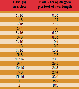
The Francis Formula indicates flow rates for weirs as gallons per minute per linear foot of weir. This value is based on the head or nappe thickness of water as it passes over the crest of the weir. To get a quarter inch of water over a rectangular weir with end contractions, for example, a flow of 4.5 gallons per minute per linear foot would be required.
Applying this to a vanishing-edge system, there might only be an eighth or a quarter inch of water flowing over the edge. This is simply the distance between the water’s surface and the crest or top of the edge of the weir.
In the pool and spa industry, we typically describe this head dimension in raw physical terms as a quarter inch of flow over the edge or an eighth of an inch of flow over the edge – or whatever thickness of water there needs to be at the crest of the weir to achieve the desired visual effect. In this case, a quarter inch represents 4.5 gpm per linear foot.
This should be familiar stuff: When you link the linear footage of the weir with the head dimension, you are ready to establish the flow rate over the edge.
The challenge of calculating weir flow rates gets more interesting depending upon the type of the weir and its shape, pitch, surface material and more. There are formulas that can be used with triangular, parabolic and trapezoidal weirs, to name a few, because all of them have different flow characteristics. Happily, we in watershaping deal primarily with rectangular weirs, which are not nearly as complicated as some of the systems you might encounter in, say, industrial materials-handling systems.
In fact, calculating the flow over a weir is not difficult once you understand the basic principles and learn to apply some calculations that should already be familiar to watershapers.
SCHOOL FIGURES
In doing so, you can take one of two paths: the Francis Formula or basic water-displacement calculations.
| Figure 3: The weirs in slot-overflow systems have no end contractions enclosing their sides (left), while those in vanishing-edge pools have contractions that affect the way water flows across the weir (right). |
Both have limitations: On the one hand, the Francis Formula only accounts for the flow at the weir and does not accommodate a swimming pool’s displacement or water in transit. (This water-displacement factor is important because it lets you know if the surge capacity is large enough to handle the flow of the weir and all of the water in transit.) On the other, water-displacement calculations are quite simple, but they are limited because they only work if the reclamation time of water displacement matches up with the pumps.
For detailed information on the Francis Formula, see the sidebar below. As for water-displacement calculations, they use the fact that a cubic foot of water is equal to 1728 cubic inches (figuring the volume of a cube 12 inches high by 12 inches long by 12 inches deep creates a “vessel” that holds 1728 cubic inches). Moreover, we can look at that cubic foot of water has having 12 layers that cover 144 cubic inches each (Figure 3, above).
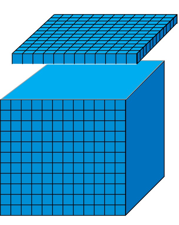
| Figure 4: A cubic foot includes 1,728 cubic inches and contains 7.48 gallons. As seen here, a one-inch slice of the cubic foot includes 144 cubic inches of water. |
To determine the volume of a quarter inch of displaced water, do the following calculation: Multiply 144 cubic inches by the surface area of the pool, then divide by 1728 to determine cubic footage, then divide again by four to get down to a quarter inch of water. Now multiply by 7.48 to translate the quotient into gallons (Figure 4).
This is important to understand, because basing your weir flow rate on water-displacement calculations can be risky: As mentioned above, it only works if the reclamation time from the surface area of the pool matches the pump’s flow. Thus, a pump with an output of 90 gpm can flood a 20-linear-foot weir wall (that is, raise the water a quarter inch) by generating a flow of 4.5 gpm per linear foot (see the table in the Francis Formula sidebar, below).
|
A Formulaic Approach Civil engineers use several equations to determine flow rates of flumes, canals and rivers by simply measuring water depths at weirs. The most important of these was developed by James B. Francis (1815-1892), a British-American engineer and founding member of the American Society of Civil Engineers.
Q = 3.33(LH1.5 – 0.1nH2.5) where Q = Flow rate over the weir in cubic feet per second (ft3/sec); L = Length of weir opening in feet (ft); H = Head of water in feet (ft); n = Quantity of end contractions (usually 0 or 2, but maybe more*) Here’s the same equation, expressed in more user-friendly units for watershapers: q = 36Lh1.5 – 0.3nh2.5 where q = Flow rate over the weir in gallons per minute (gpm); L = Length of weir opening in feet (ft); h = Head of water in inches (in.); n = Quantity of end contractions (usually 0 or 2, but maybe more*) * If the weir is contracted, use 2 as the value for n because there are two contracted ends. In the world of watershaping, the formula works out as follows: [ ] Assume a 20-by-40-foot, rectangular, slot-edge pool was designed to operate at 1 gpm/ft. The pump is selected to provide 1 gpm/ft x (20 feet + 40 feet + 20 feet + 40 feet) = 120 gpm total. After operating for several months, however, the pool has settled and measurements show the flow is one-sixteenth of an inch too low in what is now a dry part of the edge. What additional flow rate is required to get the entire edge wet again?Using the Francis Formula, q = 36Lh1.5 – 0.3nh2.5 = 36(120 ft)(1/16 in.)1.5 – 0.3(0)(1/16 in.)2.5 = 67.5 gpm. In other words, we must now increase the flow rate by approximately 56 percent to keep the edge wet. This will increase friction, however, and actual energy usage will probably double. [ ] A five-foot-wide waterfall is required to maintain a clear unbroken sheet for a vertical drop of 5.5 feet. What flow rate is required? From the tapered weir design, it is determined that a head of one inch is required to maintain a clear unbroken sheet for a vertical drop of four to six feet. Here, q = 36Lh1.5 – 0.3nh2.5 = 36(5 ft)(1 in.)1.5 – 0.3(2)(1 in.)2.5 = 179 gpm.*** It is generally accepted that the Francis formula has approximately a two-percent margin of error. This is basically negligible in system design, because there are other variables (such as friction loss in the plumbing) that otherwise affect the selection of a pump.
In addition to the limitation mentioned in the accompanying text, another limitation of the Francis Formula is that it requires the approach velocity of the fluid behind the weir to be low. This is not an issue for spa spillovers and edge systems, but it may result in prediction of lower flow rates than are actually measured when channels or runnels discharge over a weir. This is common with single spa spillovers. Note as well that triangular, trapezoidal and circular weirs do not follow the Francis Formula. When designing custom weirs other than flat ones, it’s probably best to get the help of an engineer. — David Peterson |
If the surface area of the pool is about 578 square feet, the 90 gpm flow will lift the surface of the pool the requisite quarter inch and the pool will reclaim itself within about a minute. At this point the pump and the pool surface area are said to reclaim each other.
If the pool’s surface area doubles to 1,156 square feet and you still want a quarter inch of water to flow over the edge, it would be incorrect to double the flow to 180 gpm. This is the subtle difference that leads many watershapers to oversize their pumps and plumbing. The point is, the weir design always dictates the flow rate: In that respect, even though water-displacement calculations are an integral part of these watershape design, the Francis Formula is needed as an accurate means of determining the flow rate of the weir.
SIMPLE STEPS
Focusing on simplicity, consider what it takes to make water rise a quarter inch over the edge of a swimming pool and thus spill over a vanishing edge or into a slot.
All that’s needed here is a determination of the weir flow rate in inches and then ultimately in gallons. If you can do these simple calculations, the great thing is that the same process can be used to manipulate and gain control of the type of effect created by the flow over the weir. If, for example, you wish to create a more vigorous flow, then use a half an inch as the basis of your calculations rather than a quarter inch. And if you’re working on a waterfall, use a full inch or even two or three.
These are simple calculations, of course, but there’s more to the task at hand when it comes to establishing required flow and producing desired aesthetic effects. In fact, I’d say that the physical configuring of the weir with respect to materials of construction as well as slope, direction and pitch are at least as important as getting the flow rate correct.
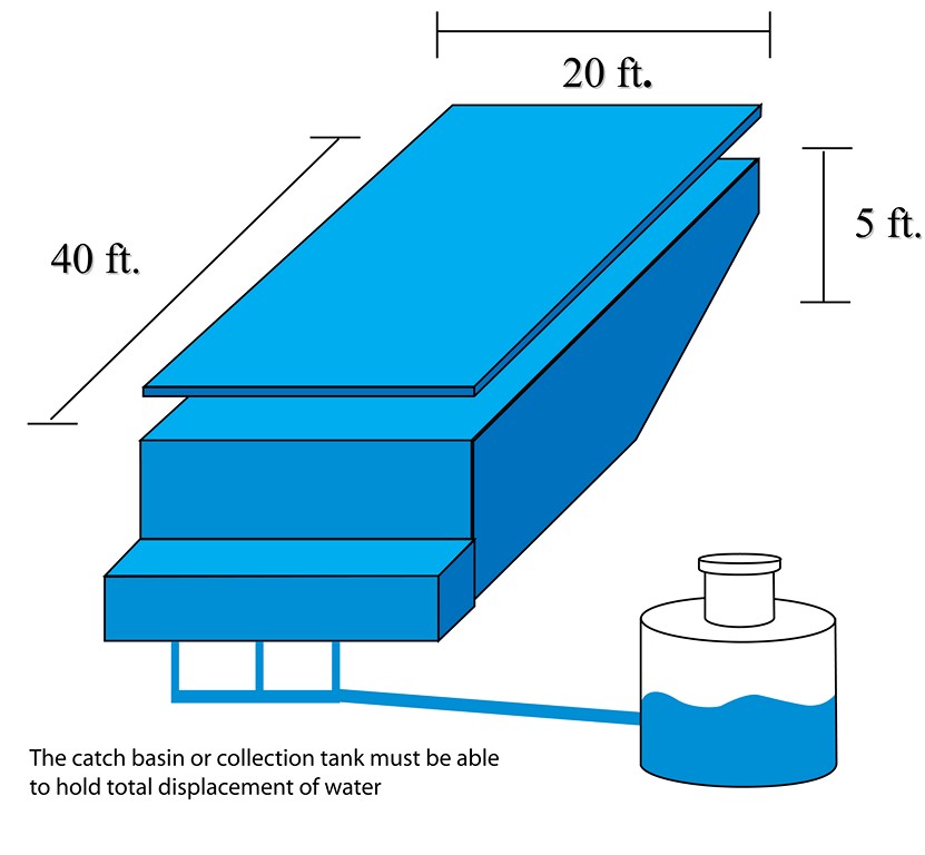
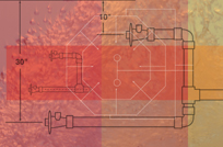
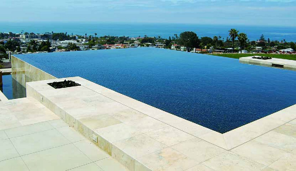
| Figure 5: In this vanishing-edge pool, the surface area is 800 square feet. Knowing that, you can multiply 800 square feet by 144 cubic inches and get 115,200 cubic inches. Dividing that by 1,728 inches, you come to 66.7 cubic feet – which, multiplied by 7.48, translates to 499 gallons. If you divide that by four, you know that displacing a quarter inch of water sends about 125 gallons over the weir. |
Through the years, I’ve often worked with Skip Phillips on weir designs for his vanishing-edge and slot-overflow pools and spas. The owner of Questar Pools & Spas in Escondido, Calif., co-founder of Genesis 3 and well-respected expert on the practicalities of hydraulic systems, he has been building vanishing-edge pools globally for more than 20 years.
Through those years, he’s developed some touchstones for weir design, saying he keeps his flow rates on vanishing edges in the vicinity of five gallons per minute per linear foot of edge, while with slot overflows that rate can be as low as two gallons per minute per linear foot.
To him, however, it’s at least as much about edge tolerance and understanding a specific weir’s configuration. He uses charts for flow-related guidance (Figure 5, above), but generally speaking, Phillips says, “The sharper the edge, the lower the flow; the larger the radius at the crest of the weir, the more flow will be required.”
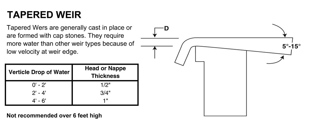
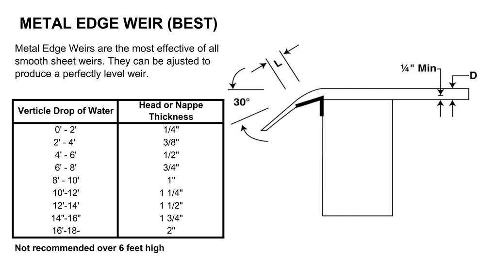
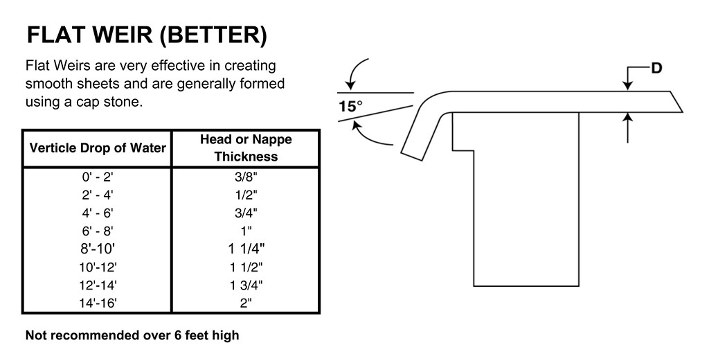
| Skip Phillips uses these charts to help him in determining flow rates for his water-in-transit details – one of many tools available to watershapers. |
While such touchstones are useful, approaching this part of watershaping as a science rather than as a casual exercise can have its advantages in developing systems that perform well (and as expected) and won’t end up costing more than they should. As mentioned above, it’s all about creating a great visual effect and doing it in such a way that all the client has to do is enjoy the sights and sounds of water flowing as intended over you well-designed weir.
The author gratefully acknowledges the assistance and support of David Peterson (Watershape Consulting, Carlsbad, Calif.) and Skip Phillips (Questar Pools & Spas of Escondido, Calif.) in assembling this article.
Steve Gutai is Director of New Product Development, Hydraulics and Heating Systems, at Zodiac Pool Systems, Vista, Calif. He may be reached at [email protected].