


An Edgy Detail

It’s true for any watershaper: No matter how varied the work you do, it never hurts to be known for the ability to do something special – and for doing it exceptionally well.
Through the years, for example, my firm has polished its ability to provide our clients with watershapes reflecting a wide variety of tastes, styles and features, but to an extent that sometimes surprises even me, we’re known among prospective clients for our perimeter-overflow systems.
And it’s not only prospective clients: We’ve also gained this reputation within the watershaping industry, which has led a large number of you to pull me aside at trade shows or drop me e-mail messages asking me just how we design and install these features. The answer is neither quick nor simple, basically because there are many ways to execute these edges, but it’s a detail I will be addressing in this column and the next.
I do so not to provide a blueprint for executing these details; rather, my aim is to give you enough information so you can make intelligent decisions about how to proceed when clients approach you with a request for your input about this increasingly popular look.
Before we begin, let me say that this is not a detail for beginners. It requires tremendous skill in developing clear and explicit plans as well as expertise in forming shells, configuring plumbing systems and shooting or pouring concrete. It’s also a costly look, so if you miss the mark in either design or installation, your nightmares are only just beginning because setting things straight after the fact can be supremely difficult without starting over.
WHAT’S IN A NAME?
Water-in-transit effects have become incredibly popular in recent years. If you look at brochures for high-end resorts or upscale residential and commercial properties, for example, you’ll almost always see a vanishing-edge or perimeter-overflow system of some type. There may be many reasons for this trend, but I think they can all be summed up by saying that these details spell luxury and drop-dead gorgeous in big, bold letters.
Ironically, one of the problems with these systems is that there’s a lot of imprecision in what people call them. Consider the “vanishing edge,” for example: Despite the fact that this has been the most published term used to describe these effects for more than 20 years, some people call them “infinity pools” or “infinite edges,” and there are still more than a few who call them “negative edges.”
Perimeter-overflow effects face the same issue: Are they properly “deck-level-overflow pools,” “knife-edge pools,” “rim-flow pools” or “slot-overflow pools”? The answer there is yes and no: Indeed, in my practice, none of those names is descriptive enough for our purposes, so we’ve come up with different terms for clarity’s sake.
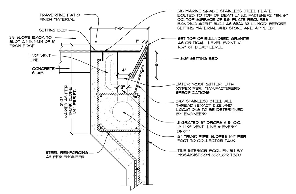
| The construction of knife-edge perimeter-overflows pools is quite complex and leaves no margin for error, and the simple fact of the matter is that every detail related to the edge must be considered and mapped out before any work begins on site. The enclosure of the gutter system in the bond beam is just one of those many details. |
One of these effects, for example, we have dubbed the “underwater-coping, perimeter-overflow slot.” That’s a hyphen-laden mouthful, but it’s the clearest way we’ve found of describing a project where we press the pool into the ground and create a slightly angled coping that lets the water flow to the back edge of the coping where we conceal a narrow slot into which the water flows. Once it flows past the edge, the water is driven by gravity into a gutter concealed beneath cantilevered deck and coping material.
Or there’s the “radius-wall overflow,” another approach in which we raise the edge of the pool above the decking and create a radiused edge over which water flows down the side of the raised beam and through a slot at deck level to reach a concealed gutter.
Or there’s what we call the “knife-edge perimeter overflow” – the most popular of the perimeter-overflow details we work with in our practice and by far the most challenging. In this detail – which is the one we’ll be focusing on in this two-part discussion – water flows to the edge of the pool at deck level and spills into a slot right at the edge of a dry deck.
When you walk up to a pool with submerged coping (as with the underwater-coping, perimeter-overflow slot described just above), you look down and see wet decking or coping material at the edge of the pool. When you walk up to a knife-edge, perimeter-overflow pool, by contrast, you look down inside the pool to the full depth of water and your feet remain dry. It’s a genuinely cool detail that creates a certain “wow” factor because those who know nothing about how these systems are made are mystified, intrigued and delighted by the effect.
This is also an expensive detail – one that can cost almost as much as the rest of the pool in some cases – and requires extremely tight tolerances. As suggested above, these pools must be done right on initial installation because the consequence of getting it wrong or having the structure fail are almost too grim to consider.
BEHIND THE EDGE
The key to success with any perimeter-overflow system is achieving a dead-level edge. In my operation, we call for a tolerance of plus or minus 1/32 of an inch. In doing so, we recommend use of a water level (gravity never lies), but I’d expect a laser level to work just as well.
To define the edge, we typically specify a 3/8-inch thick, 12-by-12-inch granite tile with a bevel on the leading edge. These tiles are installed inside the gutter at an angle that falls steeply away from the pool’s interior. The top of the bevel is the critical dead-level point and is the only part of the granite tile that will be visible.
In using this material, we butt the tiles up against one another as tightly as possible. We do so because it’s tough to establish and maintain perfectly level lines with grouted joints; moreover, we want to do as little as possible to disrupt the visual integrity of the knife-edge line.
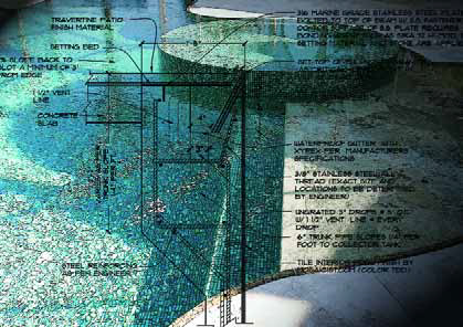
| As this plan section shows, the preparation and pouring (or shooting) of the bond beam is an intricate process involving an angled surface, a void for the gutter, some unusual steel requirements, plenty of internal plumbing and extraordinary beam width and depth. |
In already considering that line, however, we’ve jumped a bit ahead of ourselves because before that tile can be placed, you need to form and pour or shoot the gutter.
This process begins with designing a bond beam that is wider than one you’d find with a typical pool. First, the beam needs to contain the angled wall falling back from the pool’s interior, then it also has to accommodate the width of the bottom of a gutter that must be wider than the plumbing drops that will feed a trunk line that flows to a surge tank (an overall system that will be discussed in detail next time). In addition, the beam needs to accommodate the outside wall of the gutter and its vent or “snorkel” lines.
In most situations, these beams end up with widths in the 20-to-24 inch range, although one of the projects pictured here happens to have a 17-inch beam – certainly on the narrow end of the range. The beam doesn’t necessarily need to extend all the way to the bottom of the pool (although it’s recommended in areas where freeze/thaw conditions prevail), but with all that’s contained within, it definitely needs to extend down a good way toward the floor of the pool.
In our designs, we prefer to encase the perimeter trunk line within the beam – one reason they get so deep. We do so because these are gravity-fed systems in which the trunk line runs at a pitch of about a quarter-inch per foot in a typical scenario. As a result, the beam must run deep enough to accommodate the trunk line at its lowest point, which in a 40-foot run would amount a 10-inch drop. Typically, this means the beam will extend downward from the edge by about two feet.
All of this depends as well, of course, on the hydraulic system to be contained within the wall, because the desired flow rate determines the size of the plumbing. And in all cases, the structural elements of these designs, including the size and frequency of the rebar and the thickness of the wall, must be specified by a licensed structural engineer in view of prevailing soil conditions and the needs of the hydraulic system.
MINDING THE GUTTER
In the forming and concrete-application stages, perhaps the trickiest area has to do with setting up the gutters. There are a number of different ways to do so, and you also have the choice of either pouring them in place or shooting them with shotcrete or gunite.
Some people fashion their gutters in two pours, the first creating the pool wall while leaving rebar stubbed out on the outside of the wall where it is coated with a bonding agent. Then the crew comes back and forms the outside of the gutter before finishing the operation off with a second pour.
I’ve tried that approach myself, but I prefer using just one shoot or pour because I don’t want to accept the risk of leaks developing at the junction of the two pours. In addition, we also come down in favor of shooting these details rather than pouring them because when you pour the system in place, the crew must come back later to build up the knife edge by hand.
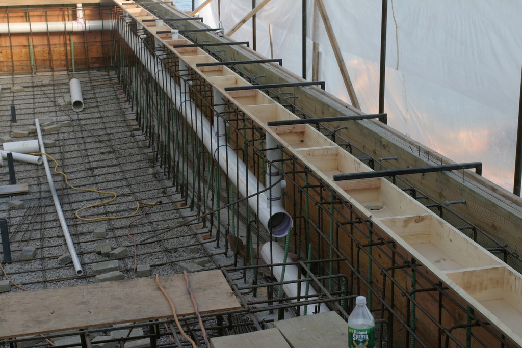
| The need to communicate clearly with subcontractors is of paramount importance, if only because what emerges from concrete application doesn’t look like a conventional pool edge. Attaining the desired precision under these circumstances calls for clear instructions, superb craftsmanship and close supervision. |
There’s no doubt, of course, that forming these trapezoidal gutters is a challenge. If the pool has a straight-line wall, the best and easiest way to do it is with a wooden form suspended over the bond beam’s form and structural steel. You can use wood with a curvilinear edge as well, but it’s obviously going to be far more difficult to do. That’s why some people use Styrofoam forms suspended over the beam to form their curved gutters.
(Another critical element has to do with providing structural support for the wedge of angled wall that forms the forward face of the gutter to which the granite tile will be applied: We always specify the use of stainless steel rebar stubbed up at an angle or insertion of threaded stainless steel bar stock because it isn’t possible to get adequate concrete coverage in this narrow section.)
Whatever concrete-application strategy you use, the plumbing for the gutter must be integrated into the forms. We typically use either three- or four-inch drop pipes to accommodate the desired flow rate and anticipated bather surge as well as the need to allow debris to flow into the trunk line and ultimately into the surge tank. (We never grate the tops of the drop lines for that reason.) We run the drop pipes at five-foot intervals, so the gutter form must have holes in it where the plumbing will be stubbed up into the gutter opening and capped, preferably under pressure.
On the drop pipes, we install tees with reducer bushings that create one-and-a-half- inch lines that we elbow up and then elbow back into the side of the gutter. This creates a vent or snorkel that allows air to flow through the system, thereby reducing the gurgling noises that can be associated with perimeter-overflow systems when the water’s line velocity is too fast for the piping. This is an extremely important detail: As a rule, clients who are paying tens of the thousands of dollars for this visual detail are not happy when the system becomes an inordinately loud auditory one as well.
(We’ve also experimented with another approach in which the drop lines are installed horizontally in relation to the gutter. This works well, but it requires an even wider beam to contain the trunk line or, alternatively, installing the line outside the concrete structure. Frankly, we’ll always opt for including the plumbing within the beam to eliminate any chance that earth movement will warp the line and impair its smooth, gravity-fed functioning.
WATER TIGHT
Waterproofing is another important factor in installing the gutters for perimeter-overflow systems, basically because you can’t afford to have them leak. Indeed, I believe in using redundant waterproofing systems, specifying a concrete additive that will effect a seal (such as Xypex, supplied by Xypex Chemical Corp. of Richmond, British Columbia, Canada) then applying layers of some other type of surface waterproofing agent as well.
Again, this is critical because the wedge-shaped slice of concrete just inside the wall doesn’t have adequate concrete coverage near the edge to ensure sufficient structural waterproofing – another reason why we use stainless steel bars at these points.
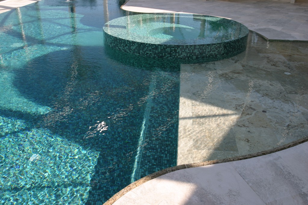
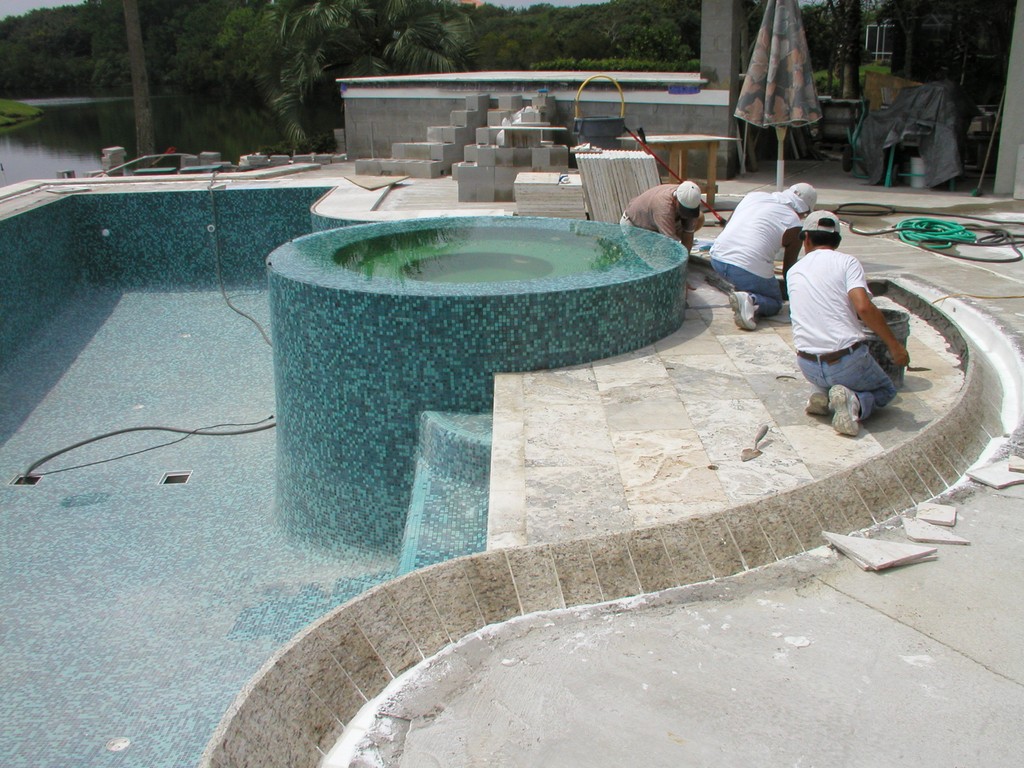
| Once complete, the knife-edge overflow is spectacular – and shows why this look has caught hold so strongly among clients who are after something really special. |
Another key question has to do with how you support the deck material that will be cantilevered over the top of the gutter. If you’re using a material that’s structurally strong on its own, you can attach it directly to the exposed top area of the beam. In the project shown here, however, we used stainless steel plating that’s 3/16-inches thick and ten inches wide with holes drilled three-and-a-half inches from the outside edge to allow us to bolt it to rebar stubbed up from the outside edge of the gutter wall. Again, all of this hardware needs to be made of materials not subject to corrosion!
The top of the stainless steel plating is treated with a steel-to-concrete bonding agent. A number of suitable products are available, including Sika 32 Hi-Mod (from Sika Corp., Lyndhurst, N.J.) or an epoxy from Laticrete (Bethany, Conn.). We’ll take the decking material and cut its forward edge at an angle matching that of the angle inside the gutter. Finally, we place the coping to leave a one-inch-wide slot – just enough space to allow for insertion of a hose to clear away any debris.
Next, a discussion of the hydraulic systems that make these edge details work.
Brian Van Bower runs Aquatic Consultants, a design firm based in Miami, Fla., and is a co-founder of the Genesis 3 Design Group; dedicated to top-of-the-line performance in aquatic design and construction, this organization conducts schools for like-minded pool designers and builders. He can be reached at [email protected].