


All the Right Angles
 By William Bennett & Walter Williams
Every once in a while, a project comes along that gives you a chance to step up and demonstrate your company’s capabilities.
The construction of the swimming pool seen here was just that kind of exercise for our firm. Located in Potomac, Md., the property is just west of Washington, D.C., in an exclusive neighborhood remarkable for the outstanding caliber and quantity of its watershaping and landscaping projects. We became involved here through a custom homebuilder who was remodeling the property and wanted to do something special in the backyard.
This represents a perfect example of how our firm, Alpine Pool & Design of Annandale, Va., thrives in this market. Through the years, we had already worked not only with the homebuilder, but also with the architect as well as the landscape architect. When it came time to consider watershape construction, all three recommended us for the job – testimony to the fact that ever since we opened shop in 1986, we’ve done all we can to establish a reputation for high-value collaboration as part of a community of like-minded designers and contractors.
We pride ourselves on being able to execute the most challenging designs and have set ourselves apart from other players in our area by pursuing the highest possible standards in both technical expertise and client service. In this case, we knew everything was on the line, because we’d never installed a project with as complex a water-in-transit design as this before.
It was a steep learning curve, but we knew from experience that if we carefully planned each step, undertook the necessary research, consulted with the right people and adhered to our usual standards of precise construction, we could make it work and leave the client and the rest of the project team happy with the results.
A PRETTY PICTURE
As part of this community of professionals at the top of the local residential design/build market, we know that referrals fly in all directions. In many cases, we serve as a client’s initial contact point and then draw in other designers or contractors as needed, depending on the situation. In this case, however, the flow ran the other way: The remodeling project was ongoing and the basic pool concept had already been established by the time we were called.
The builder and architect brought us in to figure out how to make things work and then to do the installation. The owner’s primary residence is in Greece, so we couldn’t rely on direct contact with the client; instead, we had to pull all of our cues from what the design principals had done to that point and move forward as a team.
While the basic concept was already in hand, nothing at all had been done by way of specific construction specifications, structural engineering, hydraulic design or materials selections. And while we may have had the inside track with the design team, the owner wanted other firms to be in on the bidding.
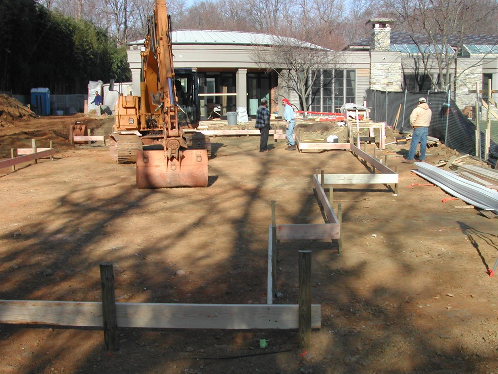
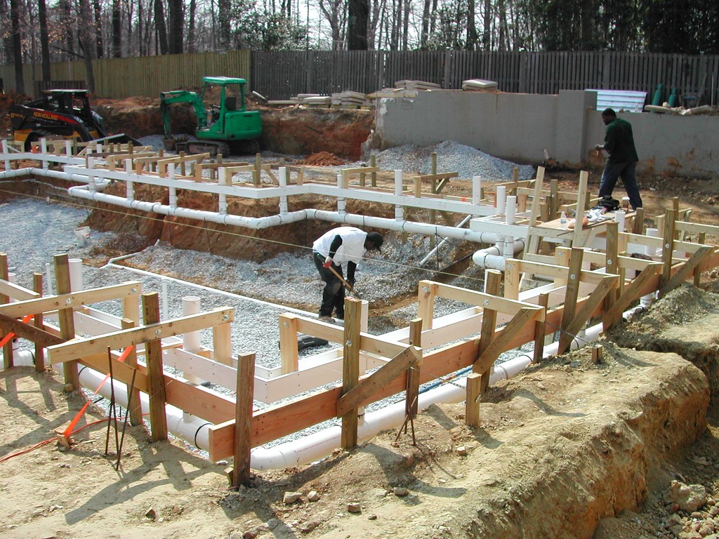
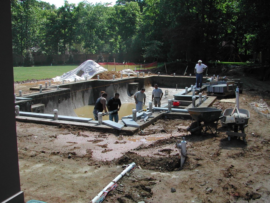
| With this project, the need for on-site precision truly began right away. We took great care in laying out basic forms for the pool, in excavation – and particularly in setting up the unusual armature we needed to support the forms for the gutter system and all of its angles. |
It helped, of course, that we’d worked with all of these people in the past and knew something of their tastes and the level of participation and support they expected. There was also the fact that the plan was so underdeveloped that some of the other companies had trouble offering firm bids. We faced the same situation, of course, but we dug in, did the research and developed a complete, detailed technical design. After a process that lasted several months, we were finally awarded the contract.
As for the original plan, it looked as though someone had gone crazy with right angles. The home’s architecture is what might be called “subdued contemporary” and features lots of mostly simple rectilinear forms along with soft, organic colors. It’s not a bold statement, in other words, and instead harmonizes with its verdant surroundings rather than standing out in the setting.
It was left to the pool to carry the modernist banner by playing off the home’s style and amping things up a bit with lots of long, straight lines accented by multiple right angles. It’s also a physically grand statement, with more than 1,500 square feet of surface area, 70,000 gallons in volume and 20 corners in all arrayed over a footprint 68 feet long, 32 feet wide and up to eight-and-a-half-feet deep.
Most of the full-perimeter, deck-level overflow designs we’ve done haven’t been nearly so large – nor did they boast such complex, angular shapes. In doing our homework, we knew right away that the size and linear complexity would make everything more challenging in the design and construction processes.
ON THE BEAM
Before we began, an old, existing pool had been removed along with a series of walls and other hardscape elements in the landscape. Although everything was to harmonize with the new pool, the actual landscape work was to be done by others: Our scope was limited to the pool, the coping system, the surge tank and the equipment area.
The narrow focus probably helped as we boiled our challenge down to a few key factors mostly related to the design of the bond beam that would contain the overflow trough and associated plumbing – and to observation of tolerances within a sixteenth of an inch, which was no small factor given the great length of the edge.
As it developed, the beam grew to be 29 inches wide compared to the 14 inches we specify for more typical pool designs. It had to be that large to accommodate the cantilevered wet coping as well as a six-by-six inch trough (positioned just off center within the beam) over a six-inch-diameter trunk line. The trunk line follows the perimeter of the entire pool and uses gravity to feed water to the surge tank. All of this had to be planned with great care not just in terms of structural engineering, but also with respect to practical construction details.

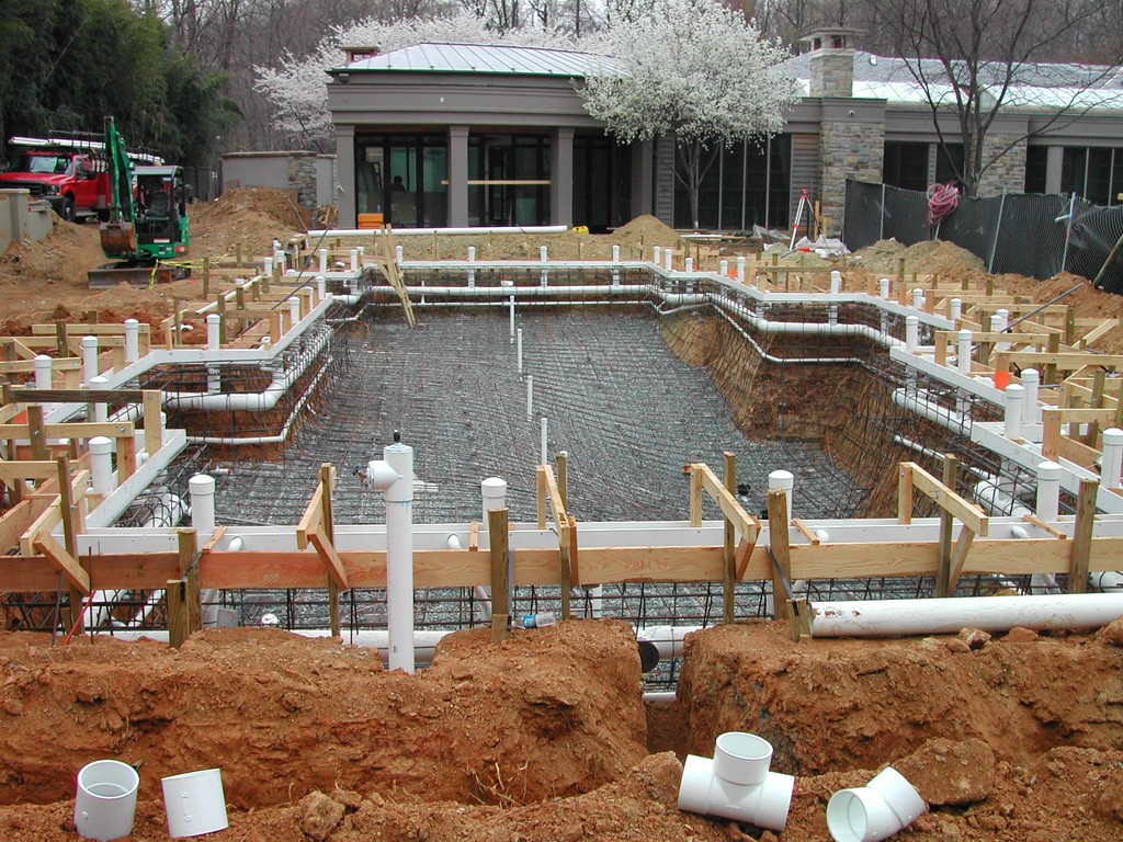
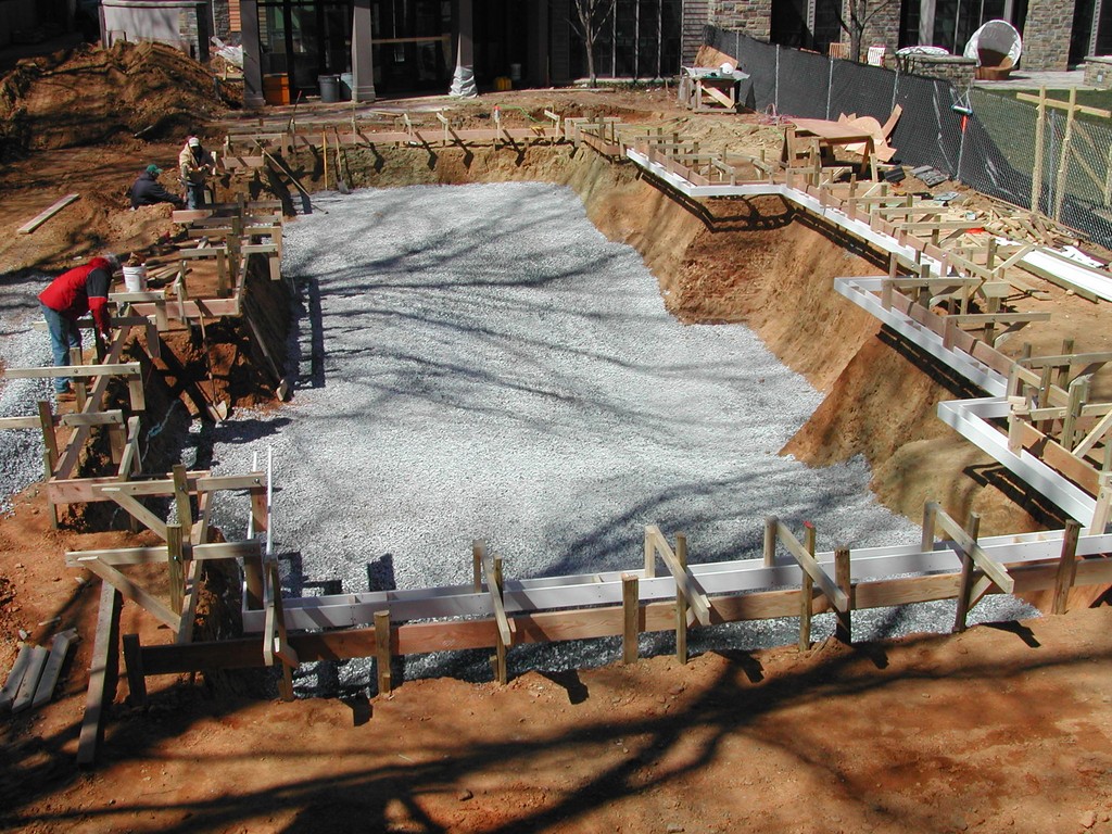
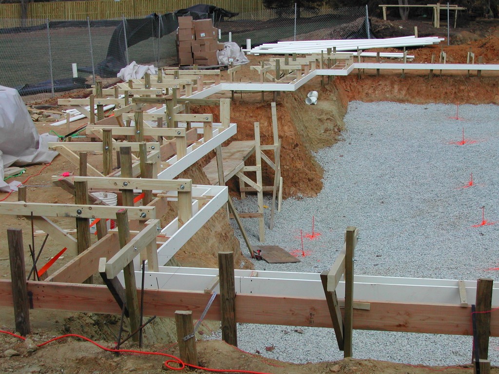
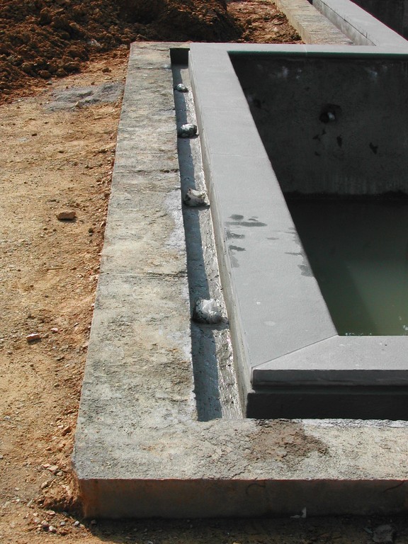
| In combination with the pool’s long perimeter, the repeated 90-degree turns in the edge detailing made for unusual challenges in designing and installing the trunk lines for the gravity-fed overflow system. In all, four separate lines feed the surge tank. |
Indeed, forming, plumbing and installing steel in the beam while including the gutter and drain systems and all their associated piping posed far and away the greatest difficulties we faced in the entire project. We considered a variety of approaches, including use of a foam spacer to help us create the gutter, but we dismissed that thought when it became apparent that it would complicate the process of setting up the drop lines between the gutter and the trunk lines: These drops were to occur at four-foot intervals all the way around the pool, and each one came with a vent line needed to reduce noise.
In setting all of this up, we had to make certain the plumber could actually install all of the required pipes; that the steel contactor could install the rebar properly; and that the gunite company’s nozzle operator had the access and angles needed to shoot behind the gutter and achieve proper steel coverage and material compaction. To make it work, we ended up fabricating gutter forms using wood and a plastic fascia material that we suspended over the beam using a cantilevered brace system.
It was a huge and (literally) lengthy undertaking, because the “box” that forms the gutter had to be suspended firmly in place while serving as a functional benchmark from which every subcontractor worked right up through concrete application.
We set up the suspended braces once the pool was excavated, sinking posts just beyond the perimeter of the pool and attaching panels to support a system of two-by-fours that hung over the beam and from which we hung the gutter forms. This preparatory phase alone required tremendous planning and fabrication before we even started working on site.
GETTING READY
The original plan called for construction to begin in November, which was unrealistic given the severity of our winters. We approached the general contractor and explained that delaying the start of activities until spring would not be time wasted, as we would use it to prepare for the installation in such detail that we could jump on things at full speed when the weather broke on or around March 1.
|
Tile Aside Early in the design team’s discussions, it was generally agreed that we should explore the possibility of using an all-glass-tile finish for the pool’s interior surfaces. In fact, the client had gone so far as to purchase a beautiful mass of tile – but that was before we decided to move in another direction. It all boiled down to concerns about freeze/thaw conditions triggered by one of our masons, who expressed strong fears about the pool being closed from sometime in November through April, during which time a crushing, expanding sheet of ice anywhere from two to six inches thick might form on the pool’s surface. We stuck to the original all-glass plan until after we shot the pool shell. In surveying the interior of the pool and its carefully shaped coves and curved offsets around four sets of steps, we began to appreciate just how difficult tiling the interior would be – even with the one-inch tiles that had been selected. So even though we believed that concerns about tile installation and durability could’ve been accommodated and that, ultimately, glass tile would’ve been a fine choice, caution carried the day and the client opted to change materials. So now the pool is finished with a black exposed-aggregate finish from Pebble Technology (Scottsdale, Ariz.) – a rich-looking surface that does a wonderful job of enhancing the reflective qualities of the water. (The client also asked us to seed fool’s gold into the finish to create golden sparkles.) Best of all and happily for all concerned, the owner is thrilled with the look – and of the five homes he currently owns around the world, says this one is the favorite. W.B. & W.W. |
The original plan had called for installing an all-glass-tile finish in the pool, but concerns over damage from freeze/thaw conditions caused the owner to move on and select an alternative. (For more on this process, see the sidebar at right).
Everything else, however, moved forward without hitch or hesitation. We used the winter months to fabricate the gutter forms and carefully plan, review, revise and finalize the steel and plumbing plans. This also gave the plumber the opportunity to mock up the manifold, drop-plumbing and vent-line systems – and to secure all of the oversized fittings he’d need before work began on site.
Basically, this preparation meant we showed up on site and tackled the installation with everyone knowing exactly what they were to be doing and when, every step of the way.
All that work truly paid off when we started on site, but the challenges weren’t rendered any smaller by our preparations. For starters, excavation required unusually precise contouring to accommodate the pool’s shape. In addition, the forms for the gutter system all had to be suspended over the beam with virtually no room for error – and the same was true of the installation of the slightly sloping trunk-line plumbing.
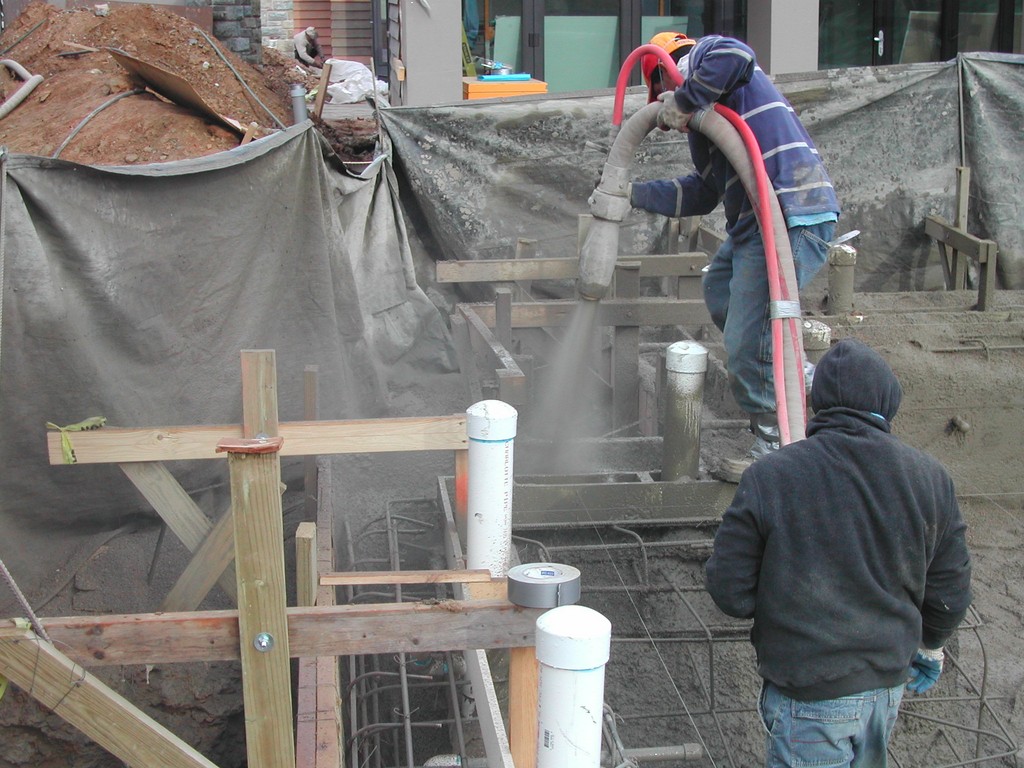
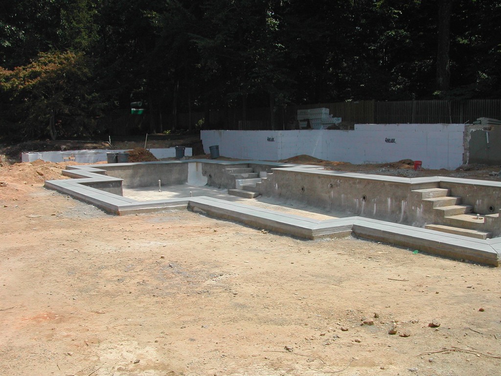
| Shooting the shell was another challenging process, simply because there was so much going on in the walls of the pool and the bond beam. When the process was complete, we removed the gutter forms and armature and began working on the finish details. |
As it turned out, meeting these challenges was most difficult on the outside 90-degree angles – spots where our subcontractors had to support the weight of heavy material as each section was carefully installed and secured in place. It was all back-breaking, precision work, and we did it knowing there was basically no wiggle room.
Consider this: On those outside corners, you couldn’t really rig the support at 45-degree angles, so in places where the material hung out over the pool, it had to be supported at right angles from two sides. That all took a great deal of time and care.
BALANCE POINTS
We also knew from the start that getting everything right for the gravity-fed drainage system would be a major hurdle. The edge system for this pool spans more than 200 feet: With a quarter-inch drop required for every linear foot of the trunk line, this meant we couldn’t possibly run the entire system as a single line. In fact, if we’d tried it that way, it would have involved an unmanageable vertical transition in the plumbing. Even with two separate loops, we still faced a drop that would have amounted to approximately 36 inches for each line! The alternative we developed required use of four separate exit points, each of which ultimately led to the surge tank.
Even working with four loops, however, accommodating the slope meant we had to build a scaffold system for the plumbers to use, simply because of the unforgiving weight of the six-inch lines and all their associated lines and fittings. Just setting up supports along the way was a major task – and a critical one as well.
We decided very early on that the trunk lines should be encased entirely within the beam. To be sure, we could have allowed the lower portions of the trunk lines to extend below the bottom of the beam, but given local freeze/thaw conditions, we decided that would be an unnecessary risk. From the start, in other words, we knew we were going to end up with a bond beam of truly massive proportions.
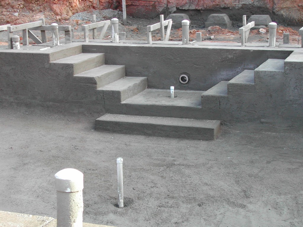
| In laying out the edge stone, cutting the miters at all those corners and setting up the coping system, we truly came to appreciate the value of the care we’d put into the early stages of the construction process. It was still challenging because of the length of the edge and the number of turns, but everything moved forward smoothly. |
On paper, this all looked pretty straightforward, but when push came to shove and we had to account for all the weight of the gutter form as well as the plumbing and all of those fittings, drop lines and vents, the work became incredibly challenging in a physical way.
In retrospect, we’re incredibly happy we had all that time to plan our course of action. Because we had been able to think through every detail, we ran into few surprises and generally didn’t have to worry about “making things work” on site. That was a good thing, and we shudder to think what might have happened had we been forced to come up with solutions for those tricky outside corners on the fly!
What we learned in this process is something everyone who’s worked on a complicated water-in-transit design knows only too well: It’s apparent right from the start that every single element influences all that follow in a sort of domino effect. In addition, in this case we saw the immediate value of a bias toward care and quality, because we knew the system was to be forever encased in the biggest bond beam we’d ever encountered.
The six-inch line that was so hard to lay out and install began with the fact that we anticipated a flow of three-and-a-half gallons per minute per foot over the edge. Calculating from that starting point influenced the size of the plumbing, which in turn drove the sizing of the gutter and the beam and, ultimately, the sizing of the circulation system and the all-important surge tank.
MAKING IT WORK
As a general rule, we’ve found through years of working with water-in-transit systems that one inch of displacement in the pool generally translates to a foot of water in the surge tank. With vanishing-edge pools, we deal with this displacement by setting things up in such a way that if people are in the pool, the system is running – a functionality we cover with a simple high/low leveling system.
With a perimeter-overflow system, however, things aren’t quite so simple and there are many more considerations that come into play.
In this case, for example, the tank is set just below grade beneath a lawn area and away from the house. It has a total capacity of 2,500 gallons, which well exceeds the anticipated momentary surge over the full perimeter of the pool – a basic precaution.
In addition, we had to consider the possible influence of freeze/thaw effects. In our area, the frost line reaches to about 24 inches below grade. Here, because of the gravity-imposed slopes, the lines reach the tank at 18 inches below grade, but the tank’s main capacity is below the level of concern. This system is completely separate from the main filtration/chemical-treatment system, which is all positioned above grade at an adjacent equipment pad.
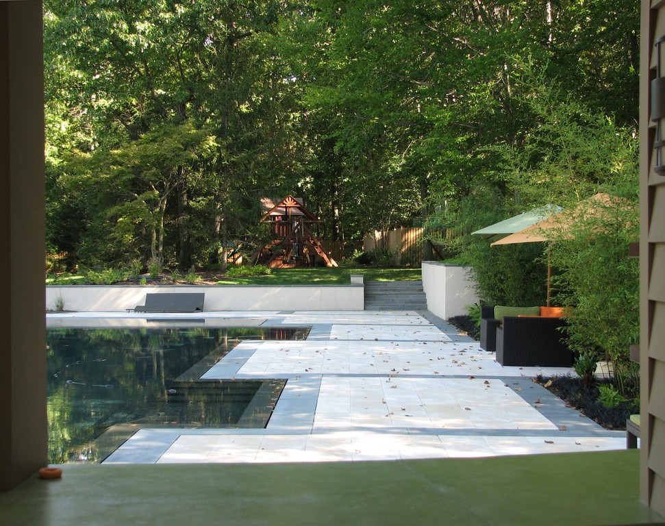
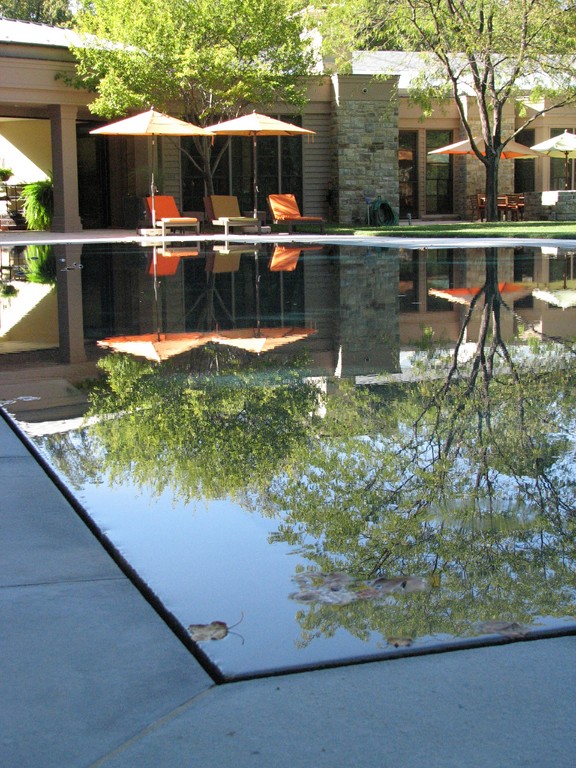
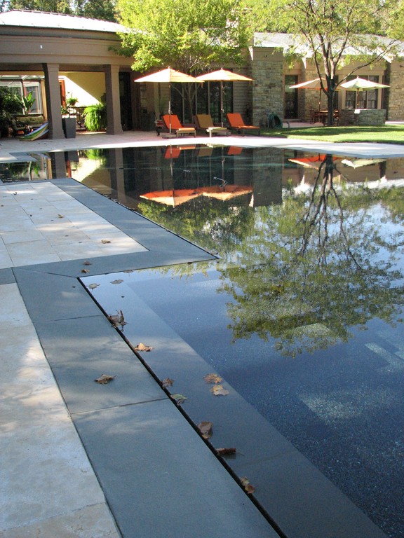
| No matter the angle or vantage point, this angular watershape perfectly suits the space it occupies – a wonderful example of architectural elements harmonizing with the overall environment and natural surroundings in perfect balance. (Photos here and the opening photo at the start of the article by Jeff Plusen, Plusen Designs LLC, Baltimore) |
The edge and circulation systems are filtered separately – a key consideration in water-in-transit systems generally, but particularly in a system as large as this one. Here, in fact, filtering capacity is oversized relative to both systems, simply because there’s a tremendous surface area to deal with – and lots of surrounding trees to keep them challenged.
The next key to making everything work was establishing the edge with the submerged coping material. As mentioned above, we weren’t responsible for the beautiful Jerusalem Stone decking that surrounds the pool with its variety of light cream and beige colors: Our work focused solely on the blue flagstone material right at the water’s edge.
The flagstone arrived precisely as ordered, but we’d asked for each piece to be slightly longer than was necessary so we could cut them to size and accommodate all of the miters required to follow the pool’s contours. The pieces had all been gauged to two inches and were basically right on – well within reach of our ultimate tolerance of a sixteenth of an inch by simple manipulation of the mortar bed.
Leaving nothing to chance at this late stage, the masons checked each stone’s thickness and made stacks of pieces they thought suitable for use as the submerged coping, which is 12 inches wide and pitches slightly toward the pool so the depth of water increases slightly to create an almost imperceptible slope leading up to the overflow channel. On the dry side, the stone also pitches slightly toward the channel to allow for recovery of any water forced beyond the slot opening.
The surrounding area slopes away from the pool, thereby letting any rain or irrigation water to run away from the pool and its gravity-fed trunk lines.
PERFECTED VIEWS
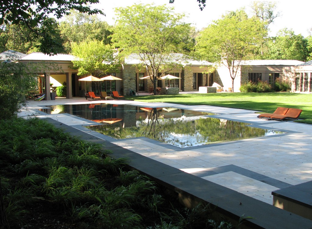
From start to finish, our objective in the studio and on site was to make the pool work as a visual extension of the home and the way its architecture blends into a backdrop filled with towering maples, oaks and poplars – and also accommodate the sculptural statement it made with its multiple angles and the inherent modernity of the perimeter-overflow system.
For all of its technical complexity and construction challenges, we see this project as expressing an idealized balance of architecture and natural surroundings. When combined with sweeping lawn areas and landscaping treatments that were beyond our scope of work, it all conspires to create a scene that is both modern in style while seeming quite contentedly organic and natural.
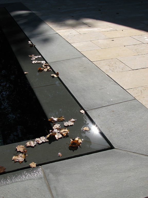
It was hard work, but in the fall of 2007, we felt proud and privileged to watch the leaves falling on the wetted edge and the beautiful decking, knowing we were in the presence of an amazing watershape that gracefully captured the spirit of a beautiful home.
William Bennett is co-founder and general manager of Alpine Pool & Design Corp., a custom watershaping firm based in Annandale, Va. He has worked in the pool and spa industry in the greater Washington, D.C., area for nearly 30 years, functioning in a variety of construction and management capacities. He founded his current firm with Walter Williams in 1987, responding to the impression that the market in their area was ripe for a firm dedicated solely to sophisticated, custom designs for affluent residential properties. Walter Williams is co-founder and principal designer for Alpine Pool & Design Corp. A graduate of Western Washington University, Williams has more than 30 years’ experience in the construction industry and has partnered with William Bennett since their firm’s inception in 1987. Williams now focuses primarily on technical and aesthetic design work, serving as the clients’ ongoing consultant through all project phases.