


The Cutting Edge


A couple months back, the National Association of Home Builders held its annual convention in Orlando, Fla. – a massive January affair that drew more than 120,000 attendees to view all manner of products falling under the broad umbrella of “home construction.”
One of the annual centerpieces of NAHB’s event is the New American Home program. Each year, select local contractors build a state-of-the-art home in the show’s host city to put the absolute cutting edge of residential design and construction on display. During the convention, show organizers sell tickets for tours, and thousands of people tour the home. Once the tours are concluded, the home is sold and becomes a deluxe private residence – and a lot of money from ticket sales flows to charity.
I was fortunate enough to be asked to design the swimming pool for the home built in conjunction with the Orlando show and have been pleased to hear that the pool drew a fair share of attention during the tours. In fact, it will eventually be featured in an HGTV television special about the project.
THE CHALLENGE
My participation began with a call from a pool builder, Michael Manley of Champagne Aquatech Pools in Orlando, who was already involved with the project and asked me to come aboard. He’s a friend of mine, a quality builder, and I’ve done design work for him in the past. Shortly thereafter, I met with the general contractors, Goehring & Morgan, a builder of high-end homes in the Orlando area.
The home has a Mediterranean-style design in a relatively tight lot that offered only a boxed-in courtyard as a setting for the pool. The house abuts two sides of the courtyard. The third side is a wall, and the fourth is a roofed shade structure. Kim Goehring told me they wanted a beautiful pool in the space but also wanted to leave enough room so the courtyard could also be used as an entertainment area.
This led to an initial key decision to push the pool up near the wall, thereby maximizing open deck space adjacent to the shade structure. We also discussed using the pool to extend some of the architectural details found in the home (including its arches) as we worked toward a simple, striking design that had both a classic shape and a contemporary feel.
The pool is almost square, with contoured, radius corners and a large, shallow, semi-circular lounging shelf on the end closest to the shade structure. Opposite the shelf is an electronic-ignition gas fireplace/chimney structure fronted by a sheeting waterfall. The pool is finished in dark cobalt blue Kolorines tile provided and installed by Ray Corrall of Mosaicist.
To the best of my knowledge, this is one of the only all-tile pools in the Orlando area, which is somewhat surprising, and is apparently one of the few such watershapes in all of Central Florida. This makes me suspect that the striking tile finish is one of the big reasons the pool received so much attention during the home tours.
Another reason the pool stands out is the use of a knife-edge, deck-level perimeter-overflow treatment. We took this path to create a crisp, dramatic relationship between the deck and the water. It was also in keeping with the state-of-the-art nature of the entire project, as these perimeter-overflow systems are the most difficult (and consequently least used) of all the available water-in-transit designs.
This approach allowed us to maximize the sense of the water’s presence despite the small amount of space given over to the pool. The knife-edge approach also takes up less deck space than would a standard deck-level system in which water flows into a slot set back from the pool beyond submerged coping. As the general contractors told us, they wanted to preserve as much deck space as possible to leave room for the entertainment area.
As is always the case with any perimeter-overflow system, achieving the effect required careful hydraulic design and precise construction.
BY THE NUMBERS
I bring up this project and this particular water-in-transit application largely because I’ve been asked by numerous people in the past few years to explain how such a system is designed, specifically with respect to accommodating surge capacity and the edge detail. Using this high-profile pool as a working example, I’ll answer those requests here with a look at how I arrived at the critical calculations.
First, designing these water-in-transit systems is all about calculating and then designing to accommodate a given surge capacity, that is, the water we can reasonably anticipate will be going over the edge as a result of a spike in bather load or wind.
That surge capacity can be accommodated within a trough, gutter or catch basin. Alternatively, it can be handled within a sub-grade surge tank, which is the choice we made for this project.

| The all-tile interior is another key characteristic of this pool – and seems to have been one of the reasons it attracted so much attention among those who came to see the home. |
To calculate surge capacity, you first need to know the surface area of the pool. The Orlando vessel is 22-1/2 by 19 feet (that is, 427 square feet) with an additional semi-circular lounging area with a radius of 7-1/2 feet (that is, about 77 square feet). Thus, the pool has a basic surface area of 504 square feet. Of course, we lose a bit of that area with the corner treatments, so we can comfortably use 500 square feet as our surface area.
The size of the surge tank is determined by combining the surge capacity with the volume of water required to maintain the tank at a minimum operating level of one foot. As a rule of thumb, surge capacity may be taken as two inches of depth multiplied by the surface area – that is, 500 square feet multiplied by 7.5 (just a hair over the number of gallons of water in a cubic foot) divided by six to reflect the two-inch depth. Thus, at two inches over our 500 square feet, we need a total of 625 gallons of surge capacity.
A word of warning about these initial calculations: Surge capacity can vary greatly depending upon the overall size of the vessel, wind conditions and anticipated bather load. If specific conditions dictate, you need to think past the rule of thumb!
Next, you need to factor in the collector tank’s minimum operating level, this time multiplying the surface area by the full 7.5. In this tank (which is 4-1/2 by 5 feet), there are 168 gallons in a foot of depth. Adding this sum to the surge capacity for the pool, we determine that the tank needs to hold 793 gallons, which, rounding up a bit, meant we were looking for a tank that would hold right around 800 gallons.
ON THE EDGE
With the surge calculations in hand, it was time to look at the flow over the edge – in this case, a perimeter that is 84 feet long.
For this project, we wanted a flow of approximately two gallons per minute per linear foot – significantly less than what you’d have flowing over a vanishing edge, for example, but more than enough to keep a steady flow into the slot with no dry spots.
If all you had to do was wet the edge, you could do it with a lesser flow, perhaps no more than might come from a small statue of a fish spitting a small stream into the water. The problem with that approach is that you also have to account for recovery time, that is, the time required to raise the water level back up to the edge when water is pushed out by bathers or wind.
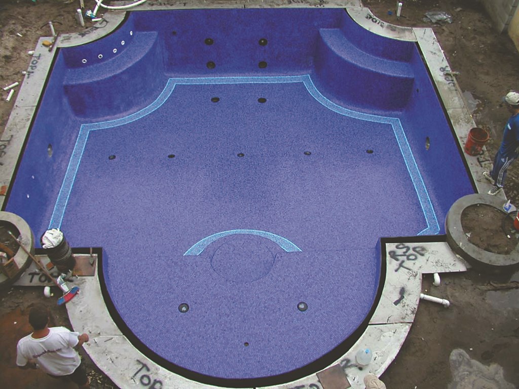
| Small but finely detailed, this knife-edge, perimeter-overflow pool represents the state of the art – and is also the most challenging to build of all water-in-transit systems. |
To achieve the desired flow of two gallons per minute per linear foot, we used a three-horsepower pump on three-inch plumbing, which gave us a flow of 160 gallons per minute. This dedicated system has two cartridge filters, in addition to the primary filter system, so we can maintain this high flow rate. With about 80 feet of overflowing edge (deducting the raised planters that interrupt the effect), we’re just over the desired two-gallon-per-minute flow rate – enough to replace splash-out up to the full two-inch surge capacity in a matter of a couple of minutes.
Once the hydraulic criteria were established, it was time to think about construction.
The surface of this sort of water-in-transit pool is defined by the edge of a narrow perimeter slot. That slot is formed as an angled edge at the water line that slopes into a formed gutter. This area is covered by coping cantilevered over the gutter and supported with 316 stainless steel in such a way that only a narrow slot is exposed.
In the Orlando application, we lined the angled side of the gutter with granite that had been ground to a rounded bullnose contour at the waterline. The top of each piece of granite is the dead-level point of the pool: Such an edge must be installed on the full perimeter within a tolerance of plus or minus a thirty-second of an inch.
In this case, we set up a six-inch-deep gutter that is four inches wide on the bottom and six inches across at the top. Four-inch trunk lines encircle the pool and are gravity-fed water from the trough, which flows to three-inch drop lines placed on five-foot centers around the perimeter.
To reduce the potentially annoying sound of water vortexing into the vertical drops and down into the trunk line, we use a special “snorkel” detail: an open-air line that connects the drop line to the wall of the gutter. This enables air to be drawn into the trunk line without creating a vortex and a gurgling noise as the water spills down the drop lines.
COMPLETING THE SCENE
Removed from the pool area are, as mentioned above, two separate circulation systems – one for primary filtration, heating and chemical treatment, the other to operate the edge effect. Because the edge serves as one giant skimmer, the system must be designed so that debris can be collected and removed from the surge tank. This means that there should be no grates of any kind on the connections between the trough and drops to the trunk line.
The tank is set low enough so that when the system is off, all of the water in the trough and trunk lines flows directly to it. Inside the tank are high/low water-leveling Levolor sensors (System Dynamics, Scottsdale, Ariz.) and a vacuum-break loop in the return plumbing – all of which are safeguards to prevent flooding of the surge tank when the system is inactive.
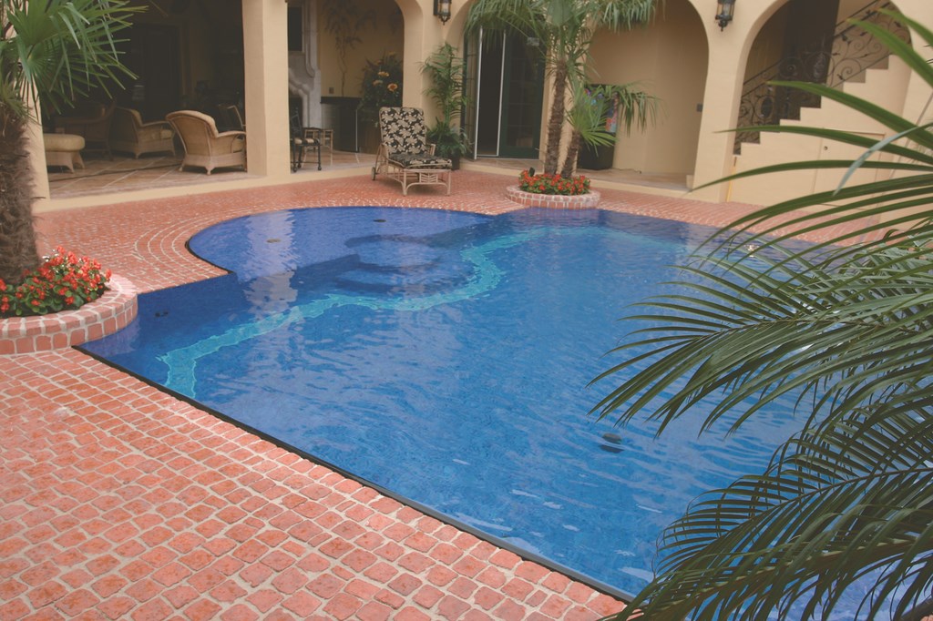
| The pool fits gracefully in the small courtyard space, fitting in visually by virtue of borrowing arched shapes from the surrounding architecture. |
When the water level falls below the lower sensor, a solenoid valve opens and adds water. If the water hits the upper level (also defined by the positioning of the overflow line), the other sensor throws a relay that is wired in parallel with the circuit for the edge effect’s pump and draws down the level in the tank. The vacuum loop serves to prevent backflow into the tank in the event the check valve in the return line fails – which in time it will, as all check valves do.
This way, we’re assured that even if the water in the tank exceeds the surge capacity, we have a redundant measure in place to prevent overfilling of the tank.
None of what I’ve described here is rocket science by any means, but it does require proper calculations and meticulous installation (not to mention complete awareness of the relationships among all of the factors I’ve discussed). When you get it right, the results can be a striking, reliable visual effect that will delight clients. In this case at least, that delight was shared by thousands of visitors to a state-of-the-art home.
Brian Van Bower runs Aquatic Consultants, a design firm based in Miami, Fla., and is a co-founder of Genesis 3, A Design Group; dedicated to top-of-the-line performance in aquatic design and construction, this organization conducts schools for like-minded pool designers and builders. He can be reached at [email protected].