


Perfect Forms

One of the things I’ve referred to repeatedly through the years is my interest in quality forming for watershapes.
I look at it this way: If the job is about creating quality reinforced-concrete structures, then precisely controlling their dimensions and contours stands at the very heart of the art and craft of watershaping. And all I’m recommending here is simply following the lead of the experts who install building foundations and structural walls by using completely rigid materials and support frameworks.
To drive that point home, I want to discuss the forming of one specific detail – and define a right way of getting it done.
One of my trademarks is the fact that I build many pools that are raised some 18 to 21 inches out of the ground. That basic chair-height dimension comes from Henry Dreyfus’ seminal work, The Measure of Man and Woman: Human Factors in Design, a fantastic treatise that looks at the physical relationships between humans and their environment.
In designing and building these low walls around watershapes, you must consider the fact that raising them usually exposes them on both sides, which means that in addition to being a key structural component of the design, they also play an important aesthetic role in the overall composition.
NO COMPROMISE
Working with raised walls in aesthetically pleasing ways means dealing with three interrelated keys that make them work: tolerances, finish materials and coping treatments.
If, for example, you are working with an above-grade pool on flat land that is to be finished on the outside face with ledger stone, the tolerances you use in setting up the wall can be a bit looser than would be the case if you were working with a more demanding material such as glass tile.
With ledger stone, the wavy irregularity of the material’s finished surface will cover variations in the finish of the concrete structure behind it. With something like pavers or tile, however, variations as small as plus or minus a fraction of an inch can spell the difference between spending huge amounts of time cutting and chipping to smooth the concrete surface or proceeding efficiently with the installation.
The nature of the coping dictates tolerances as well. For structures that are basically level with surrounding grade, the coping will be seen only from inside the pool. With a raised pool wall, by contrast, you’re creating a free-standing structure and the coping becomes a form of wall cap. Again, if you’re using a rough-cut natural stone, a bit of play in the underlying concrete structure probably won’t amount to much visually. But if you’re working with a dry-cast bullnose or wall cap – any material made itself with more precise tolerances – you want a much cleaner appearance, and a sixteenth of an inch can make a world of difference.
In my work, I choose to work to exacting standards in forming all of my raised walls. This far exceeds the practices I observe on most pool-construction sites, where I see forming made up of bender board and flimsy supports – that is, stakes that are spaced anywhere from 24 to 40 inches apart. Assembled in this way, these elements move like drapes in a breeze when you hit them with concrete.
Staking practices in general really get me going. I often see one-by-twos used for the purpose, and on the East Coast, I’ve even seen pieces of rebar used as form supports. (The rebar is first used to mark the layout; after excavation, bender board is tied to the steel and concrete is applied. The problem is that the excavating process undermines the rebar and allows it to move, often a good bit.) In these cases, dimensions can vary by inches instead of tiny fractions of inches, yet I’m constantly surprised by those who defend this shoddiness as coming “close enough.”
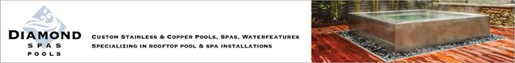
All of my forms feature two-by-four stud construction (instead of bender board) with plywood veneer and stakes with kickers at 16 inches on center. I also use two-by-four top and bottom plates, and all inside surfaces are lined with tempered Masonite. In my book, this should be the norm for any portion of a pool that is not surrounded by soil. This isn’t a high-end detail: It’s all about proper construction practices.
To be sure, we’re talking a different realm with respect to time and cost, but it’s the one sure way to ensure provision of a precise gunite or shotcrete structure. When I talk about this difference with clients, I tell them that we’re going to build a wall just as if we were building the foundation of a house.
WHY AND HOW
I have some very practical reasons for taking such an uncompromising approach to quality when it comes to forming. First of all, the alternatives – that is, the use of bender board, button board or even dry wall as a forming surface – simply don’t work as well as the materials I use.
Whenever you shoot or pour concrete against one of those inferior materials, the support structure is invariably going to flex with the weight and impact of the concrete and you’re going to lose anything approaching tight ultimate tolerances. I’ve seen jobs where an entire wall has blown out during a gunite shoot, but more commonly I see cases where the unfinished side of the raised wall against the form ends up being plus or minus three inches.
Often what happens in such situations is that to make the raised wall workable in aesthetic terms, you have to go in with hammers, chisels and chippers and remove all sorts of extra material. I’ve known clients who’ve asked, quite reasonably, why a crew is taking all that stuff off after just putting it on – and who can blame them, as it’s a manifestly dumb way to get things done.
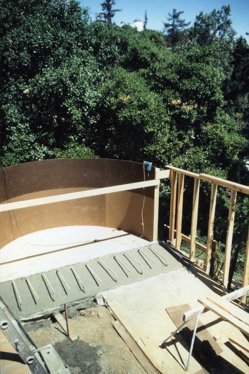
| This pool is set on piles with grade beams and is exposed to the air on all sides – one end on a grade beam, the other on compacted soil. All sides were to be visible, so the tolerances are set at a sixteenth of an inch and the forms set up for maximum rigidity with two-by-fours, plywood veneers and tempered Masonite. It doesn’t matter if the forms are eight feet tall (as these are) or just 18 inches – the same basic construction principles always apply. |
 In my work, I use solid stud construction lined with plywood because I don’t want the structure to bend at all during the gunite phase. Bottom line: Concrete forms really should not move, and if you’re among those who play these things fast and (literally) loose, you’re not building to true professional standards.
As large an issue as the forming’s rigidity is the fact that the inferior support materials will stick to the concrete and serve up a frustrating, expensive and time-consuming mess. (The same is true of plywood, which is why I line it with Masonite.)
There are three ways to finish forms for easy stripping: You can cover the wood with some form of penetrating, log or release oil. That works well, but you must be sure the entire wood surface is coated. More important, you must also be certain that none of the oil gets on the structural steel, as concrete will not adhere to the oiled steel and the structural integrity of the shell will be seriously compromised.
Some swear by lining all of the plywood with two-mil plastic sheeting tacked down with a staple or tack gun. That work just fine – unless, that is, you get a crease or wrinkle in the plastic that gets encased in concrete, which can be very difficult to remove. It’s a good material, but it’s not my particular choice.
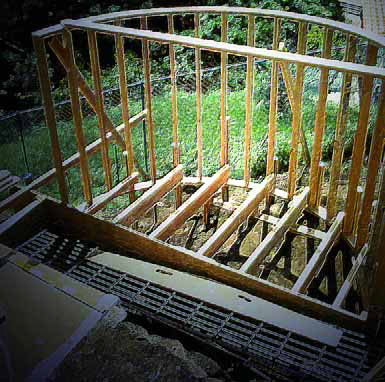
Instead, I use 1/8-inch tempered Masonite – a smooth, hard, non-porous surface. It has a rough side and a smooth side, and you want to put the rough side toward the plywood and leave the smooth side exposed. You’ll be amazed how easily it will come off later on, leaving you with a perfectly smooth surface.
CONSIDERING STEEL
Once the forms have been set, it’s time to lay the steel cage that will give the raised structure much of its structural integrity. Again, there is a right way to do it.
We maintain a reliable distance between the steel and the above-ground forming with small concrete blocks called dobies, which are either two or three inches thick, depending upon the wall’s ultimate thickness and where the steel should be within the wall to lend it maximum strength. This is similar to the familiar practice of blocking steel up off the bottom of the pool and helps to make certain the steel stays in place and is encased in concrete at the proper depth.
|
Good Practice I’m startled when people say that the construction details I describe in these columns are only for high-end clients and expensive projects. Little could be farther from the truth. Take the accompanying “Detail” as an example: What I describe in this column on raised pool walls is simply good construction practice, a method of work that is virtually certain to deliver results that will simplify the construction process, please my clients and sustain my reputation as a watershaper who never compromises on quality. To be sure, some of the work I do may seem outlandish and over the top, but if you look carefully, you’ll see that behind most everything I’ve ever done is a determination to build well-engineered structures that represent the best in on-site construction practices. If you want to fault me for that, so be it, but the upshot is that my work is bulletproof and serves my clients well, year after year. To me, it’s not outlandish: It’s just common sense. — D.T. |
In placing the dobies behind the steel, we angle them slightly off the vertical, adding a bit of tension to give the steel extra support during gunite application. A few degrees is all it takes – just enough so the blocks push firmly against the steel and makes the steel more rigid and better able to hold the blocks in place when the concrete is applied.
Where many builders seem to think that forms and steel are distinct elements, I see them as a combined, unified structure. After all, if the framing isn’t solid, the entire structure will move and the steel will vibrate with the impact of the concrete. This creates minute voids around the steel that sap the potential strength of the structure. Any structural engineer will and they’ll tell you that this is a very bad thing. At that point, the structure is essentially not being built according to the plans and specifications.
This weakness can result in all sorts of problems, including structural failure on the one hand or aesthetic problems on the other. The consequences of structural failure are obvious in the form of cracking or collapse. On the visual side, I’ve seen exposed walls where calcium precipitates form on the wall to mirror the exact pattern of the steel as a result of the chemical reactions between the concrete and any water that finds its way into voids in the structure.
Keep in mind that steel and concrete work so well together because their expandability ratios are just about identical, which makes them stable, reliable companions to one another. When you break the working bond between them – which is what happens when you have voids around the steel – the entire shell is compromised.
In other words, if you build forms that move during gunite or shotcrete application, not only are you building a structure that does not conform to any precise dimensions, but you may also be building structures that are unsound. What this all boils down to, in my mind, is that the cost of doing it right with good, solid forming and best practices in laying steel is basically what it takes to work to professional standards.
I know which path I prefer to follow.
In an upcoming “Detail,” we’ll look at the forming of troughs, dam walls and vanishing-edge walls.
David Tisherman is the principal in two design/construction firms: David Tisherman’s Visuals of Manhattan Beach, Calif., and Liquid Design of Cherry Hill, N.J. He can be reached at [email protected]. He is also an instructor for Artistic Resources & Training (ART); for information on ART’s classes, visit www.theartofwater.com.