


A Layered Approach

A little more than 100 years ago, in the first big growth spurt in the use of electricity, the harsh realities of the hazards involved with it quickly became apparent. Fires were common occurrences everywhere electricity was distributed, and serious (and often fatal) accidents made daily headlines wherever people came into contact with this wondrous phenomenon.
Virtually all of the electric works being built in those early days were set up to provide lighting for a population tired of living in the gloom of candles, gas lamps and coal-oil lanterns. That meant that electricity for illumination was being taken to homes, factories and office buildings – virtually everywhere – at the same time.
The rush was on: In their haste to serve everyone at once (and make gobs of money in the process), many entrepreneurs entered the field. The fact that very few of these individuals had anything more than a minimal understanding of electricity, combined with the lack of components and materials specifically designed for the application, might have caused the quick demise of a less desired product.
WIRES AT WORK
The major technological problem facing early providers of electricity was the poor quality of the wiring installed to convey electric current to the end user. More specifically, it was the poor quality of the insulation on the wire. In some instances, the wires had no insulation: Bare conductors were simply fastened to wooden cleats with iron staples, creating a huge shock hazard.
The best insulator of the day was rubber, but it was difficult to apply and therefore very expensive. So most of the wire used was insulated by a covering of braided cotton fibers impregnated with some form of wax.
It quickly became obvious that the answer lay in providing an additional layer of protection around the insulated wires. It was time for conduit to enter the picture.
The most successful of the earliest conduit designs was one fabricated of spirally wound paper, much like the tube in a roll of today’s toilet tissue. These tubes were made in ten-foot lengths in various diameters up to one inch. They were impregnated with a waterproofing compound, and brass sleeves were available to couple the lengths together.
Although quite popular when introduced, this paper conduit was not particularly easy to use. It was fragile and easily damaged during normal handling and installation. Wrapping a thin sheet of brass around the outside of the paper conduit during the manufacturing process improved the product somewhat, but careless installers could still crush the conduit quite easily, making it difficult to pull any wires through it.
The need for greater strength led to the next configuration – that is, placing the paper conduit inside a length of the wrought-iron pipe then in common use for the distribution of gas. Various threaded fittings were readily available to mate with the standard threads on each end of these pipes. Experiments also moved forward with other internal insulating coatings, including thin wooden strips bent to form a tube.
The required strength had finally been achieved. But as all of this development work was going on, there was a group asking themselves if the insulating jacket on the inside of the iron pipe was really necessary.
The fact that paper, wood or some other material had to be inserted into the pipe added significantly to the cost of the finished product. The insulation on the wires themselves was improving rapidly; rubber insulation had been improved and its cost was dropping. So why not try well-insulated wire in the plain iron pipe?
As it turned out, it worked just fine.
CONDUIT BASICS
At that point, there were only two minor hurdles to overcome: manufacturing methods had to be devised to ensure that the inside of the pipe was relatively smooth so that the wire’s insulation would not be damaged as it was pulled into the pipe; also, suitable coatings had to be developed to ensure that the iron pipe would not rust.
The latter problem was solved by galvanizing – that is, the application of a coating of zinc to the iron pipe. By the turn of the century, this non-insulated, galvanized iron pipe was the conduit of choice and in fact has survived to the present day virtually unchanged. (We refer to it now as rigid metal conduit.)
During the past hundred years, the number of conduit types has grown considerably. The National Electrical Code, the source of the vast majority of regulations governing almost all things electric in our country, currently lists more than a dozen types of conduit as acceptable wiring methods.
Not all of these conduit types are of immediate interest to readers of this magazine. In fact, Article 680 of the NEC, entitled Swimming Pools, Fountains, and Similar Installations, references just six types of conduit for specific applications in watershapes. The following paragraphs provide a description of each of these.
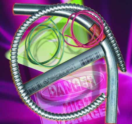
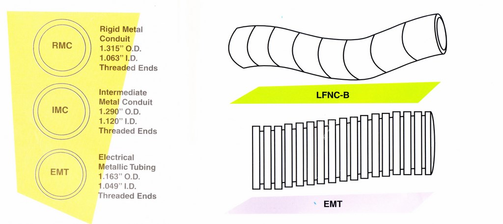
[ ] Rigid Metal Conduit (RMC), Intermediate Metal Conduit (IMC), Electrical Metallic Tubing (EMT): These three can be grouped together because they all are constructed of galvanized steel pipe. They differ in two major areas – the dimensions of the product (both inside and outside diameters) and whether the ends are threaded. The thicknesses of the conduit walls vary as shown in the diagrams below. The dimensions apply to a one-inch size in each case.
 Each of these three conduits can be bent in the field. EMT, commonly referred to as “thinwall,” is the easiest to work with. It can be bent by hand using a tubing bender designed for the purpose. The smaller sizes of IMC also can be bent by hand, but only with considerable effort.
To that purpose, there are large mechanical and hydraulic machines available for bending IMC and RMC, and pre-formed bends also are available for those not wishing to get into bending these conduits in the field. Complete lines of connectors and fittings are also readily available.
[ ] Rigid Nonmetallic Conduit (RNMC): This is a PVC product, available in Schedule 40 and Schedule 80 wall thicknesses. It looks very much like PVC water pipe, but has markings along its length indicating its use in electrical constructions. (Be aware that this is not the same product as PVC water pipe, and the two should never be interchanged.)
RNMC can be bent in the field in an oven designed especially for the purpose, but bends, connectors and fittings are readily available. RNMC and its associated components are connected together by solvent welding with a primer and solvent cement – similar to the method used to connect PVC water pipes.
[ ] Electrical Nonmetallic Tubing (ENT): The corrugated design of this molded copolymer conduit makes it quite flexible. Snap-on fittings are the generally accepted method of installation, although some specially marked products will accept solvent-welded fittings. It is not permitted for outdoor use, but it may be imbedded in poured concrete.
[ ] Liquid-tight Flexible Nonmetallic Conduit: This versatile product is available in three configurations:
* When made with an inner layer and a separate outer layer bonded together with a reinforcing webbing between the layers, it is designated as LFNC-A.
* When it is made with a single-thickness wall with the integral reinforcement molded within the wall, it is designated as LFNC-B.
* When the conduit wall is corrugated inside and out and contains no reinforcement within the wall, it is designated as LFNC-C.
Type “B” is the most common and versatile. Special fittings and connectors are available for field assembly.
ON-SITE APPLICATIONS
In Article 680 of the NEC, whenever the requirement is for RMC the text will also state that IMC is acceptable – and these two heavyweights are indeed interchangeable.
In most cases, RNMC and LFNC are also listed as acceptable alternates, but the usage of ENT and EMT is fairly limited. When the electric current for the watershape is coming from a building, either ENT or EMT may be used to protect the conductors on the inside of that building. If the conduit is attached to the outside of the building, however, only EMT is permitted. When the conductors leave the building, they must continue inside of one of the other types of conduit.
Please note that local communities may choose to adopt regulations differing from those contained in the NEC. Always check with the local authority having jurisdiction when in doubt.
Jim McNicol was a technical consultant to the swimming pool, jetted bath and spa industries. He worked on development of equipment standards for pools and spas throughout his career and was honored for his service by the National Spa & Pool Institute.